Supercharge Your Innovation With Domain-Expert AI Agents!

Stereo image display device

A technology for display devices and stereoscopic images, applied in stereoscopic systems, image communications, electrical components, etc.

Inactive Publication Date: 2007-12-26
WINTEK CORP
View PDF0 Cites 17 Cited by
  • Summary
  • Abstract
  • Description
  • Claims
  • Application Information

AI Technical Summary

Problems solved by technology

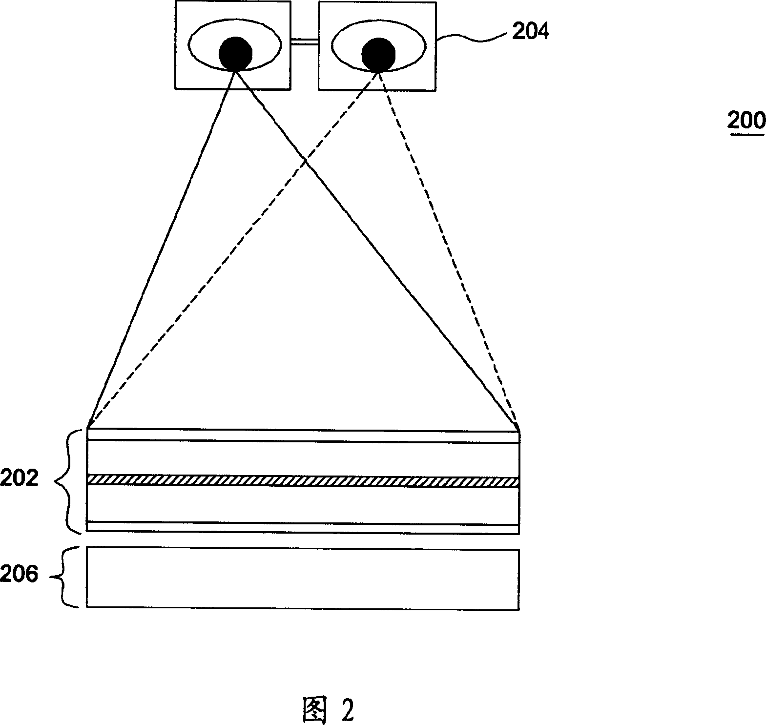
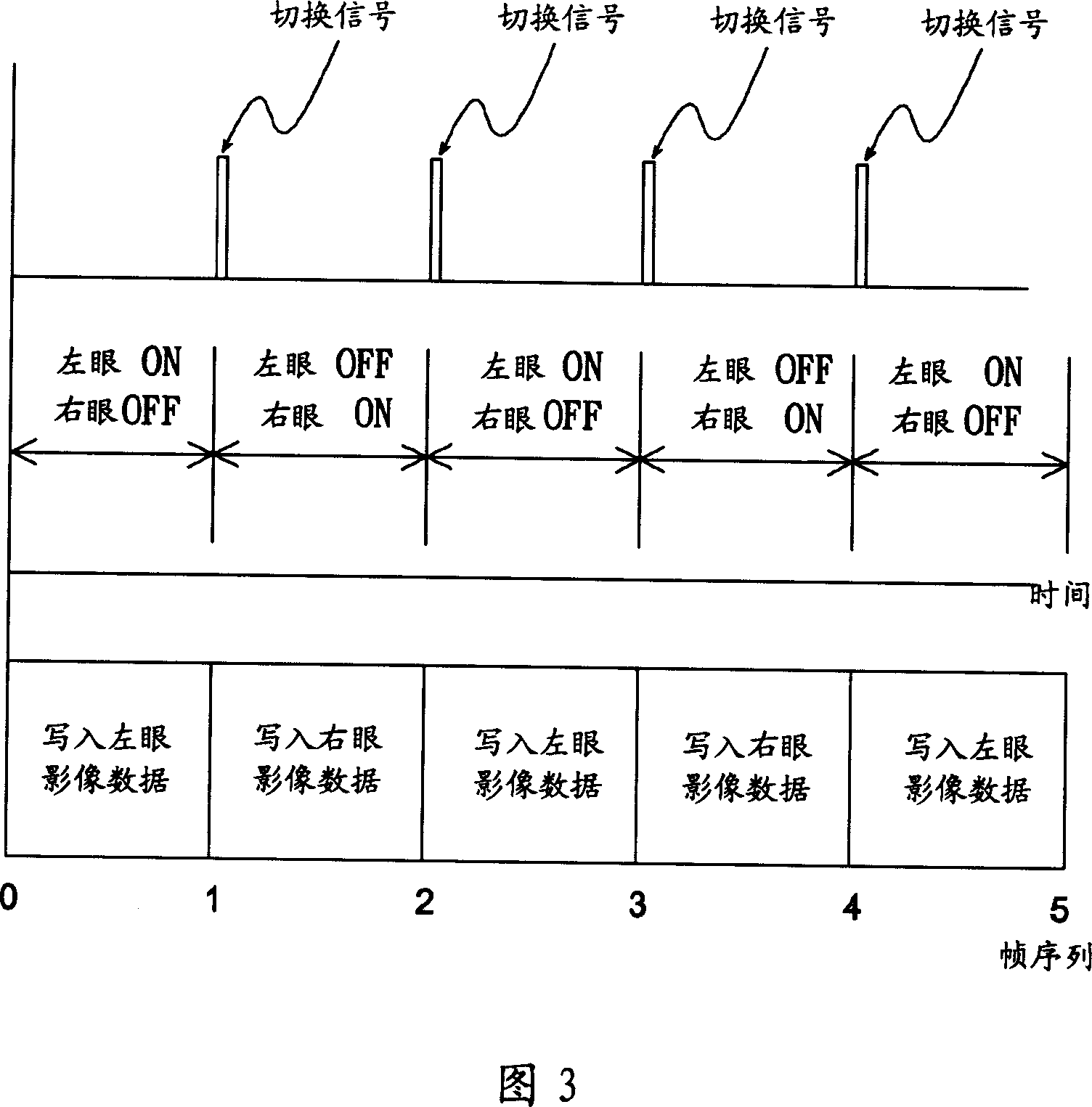
[0005] Based on the above, it can be seen that in the known designs shown in Figures 1 and 2, if a stereoscopic effect is to be produced, separate parallax image frames for the left and right eyes must be prepared in advance; and in the known design shown in Figure 4, although the The original two-dimensional image data is used as the input screen, but it is still necessary to synchronize the On / Off switching timing of the left and right eyes of the stereo glasses and the timing of image signal transmission

Method used


Image

  • Stereo image display device
  • Stereo image display device
  • Stereo image display device

Examples


Embodiment Construction

[0060] FIG. 6 is a schematic diagram showing a stereoscopic image display device 10 according to an embodiment of the present invention. As shown in FIG. 6 , the stereoscopic image display device 10 includes a display panel 12 , a first liquid crystal shutter (LC shutter) 14 , and a second liquid crystal shutter 16 .

[0061] As shown in FIG. 6 , the display panel 12 includes a plurality of red (R), green (G) or blue (B) sub-pixels, and each sub-pixel is arranged in a horizontal direction (X-axis direction) and a vertical direction (Y-axis direction) to form multiple Rows and columns. The first liquid crystal light valve 14 is disposed on one side of the display panel 12 and is used as a parallax optic to generate visual separation between left and right eyes. When the liquid crystal light valve 14 is closed, the light can completely pass through the liquid crystal light valve to form a flat two-dimensional (2D) image display mode; The transparent block 18 forms a stereoscop...


PUM


Abstract

The invention comprises: a display panel, a parallax optical component, and a brightness control component. Said parallax optical component is located at one side of the display panel in order to make users' right eye and left eye respectively see a first viewing area and a second viewing area when users watch the display panel through the parallax optical component. The brightness control component is located at user's sight line for watching the display panel, and has a first and second transparent zones respectively corresponding to the first viewing area and second viewing area; the first and second transparent zones has different light transmission rate.

Description

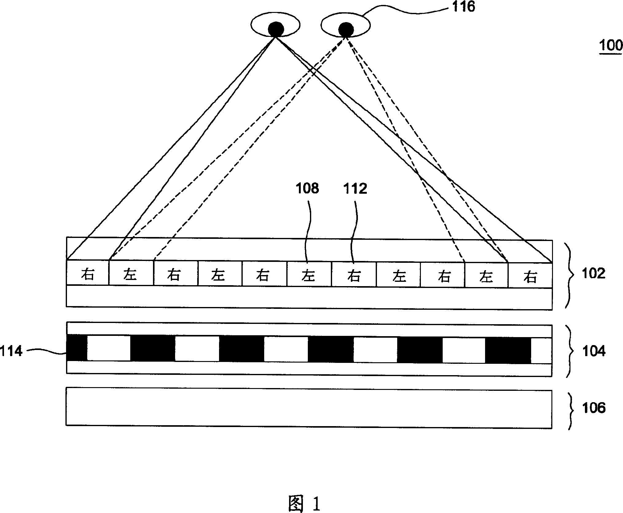
technical field [0001] The present invention relates to a three-dimensional image display device, in particular to a three-dimensional image display device (3D image display) which utilizes the Pulfrich effect to produce a three-dimensional display effect. Background technique [0002] FIG. 1 is a schematic diagram showing the design of a conventional autostereoscopic display device (autostereoscopic display) 100 . As shown in FIG. 1 , the image display device 100 includes a liquid crystal display panel 102 , a liquid crystal shutter (LC shutter) 104 , and a backlight 106 . The liquid crystal display panel 102 has a plurality of pixel units 108 for displaying left-eye image data and a plurality of pixel units 112 for displaying right-eye image data, and the pixel units 108 and pixel units 112 are arranged alternately at intervals. Furthermore, the image data for the left eye and the right eye can be produced by using two cameras arranged horizontally side by side to represe...

Claims


Application Information

Patent Timeline
Patent Type & Authority Applications(China)
IPC IPC(8): H04N13/04H04N15/00
Inventor 林汉昌吴法震
Owner WINTEK CORP
Features
  • R&D
  • Intellectual Property
  • Life Sciences
  • Materials
  • Tech Scout
  • Unparalleled Data Quality
  • Higher Quality Content
  • 60% Fewer Hallucinations
Learn More