
Structure for assembling faceplate

A technology for assembling structures and panels, applied in the installation of support structures, rack/frame structures, instruments, etc., can solve problems such as unfavorable lightweight development of notebook computers, increase in weight of notebook computers, etc., to improve reliability, reduce weight, The effect of simplifying the assembly process

Inactive Publication Date: 2007-12-26
COMPAL ELECTRONICS INC
View PDF0 Cites 9 Cited by
  • Summary
  • Abstract
  • Description
  • Claims
  • Application Information

AI Technical Summary

Problems solved by technology

[0006] (1) Since the pair of frames is usually made of metal, the configuration of the pair of frames will lead to an increase in the overall weight of the notebook computer, which is not conducive to the development of the notebook computer towards a lightweight direction

Method used


Image

  • Structure for assembling faceplate
  • Structure for assembling faceplate
  • Structure for assembling faceplate

Examples


Embodiment Construction

[0033] In order to make the above and other objects, features and advantages of the present invention more comprehensible, an embodiment will be described in detail below together with the accompanying drawings.

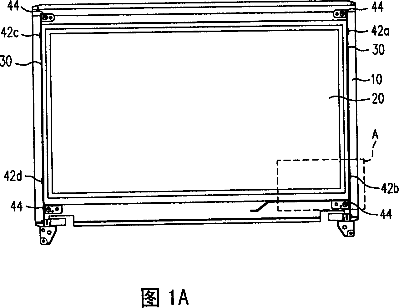
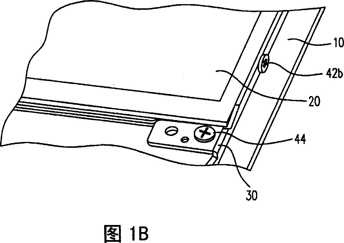
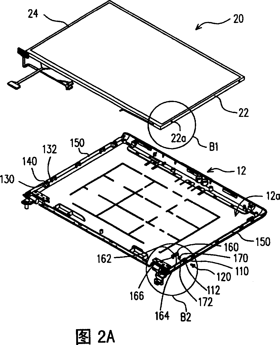
[0034] The panel assembly structure of the present invention can assemble a display panel on the inner surface of a casing of the electronic device. In this embodiment, a notebook computer and a liquid crystal display panel assembled on the panel cover of the notebook computer are taken as examples for illustration. In addition, the panel assembly structure of the present invention can also be applied to other electronic devices with display panels, such as mobile phones, language translators, digital cameras, digital video cameras, personal digital assistants, and the like.

[0035] Figure 2A and Figure 2B are a perspective exploded view and a top view of a panel assembly structure according to an embodiment of the present invention before assembling the panel to th...


PUM


Abstract

The invention is used for mounting a panel on an inner surface of a panel cap. It comprises a first conjunction unit, a first bolt, a second conjunction unit and a second bolt. The first conjunction unit is formed on the inner surface of the panel cap and extends to the first side of the panel, and has a first connection through hole. The first bolt is threaded into the thread of the first panel in order to lock the first conjunction unit and the first side of the panel. The second conjunction unit is formed on the inner surface of the panel cap and extends to the second side of the panel, and has a second connection through hole; the second bolt is threaded into the thread of the second panel in order to lock the second conjunction unit and the second side of the panel.

Description

technical field [0001] The present invention relates to a panel assembly structure, and in particular to a display panel assembly structure in a notebook computer. Background technique [0002] Since the invention of the first black-and-white television using a cathode ray tube (Cathode Ray Tube, CRT) as the working mode, image display technology has been evolving at a rapid pace. However, due to the disadvantages of large size, heavy weight, and high radiation dose, such a display operating in the cathode ray tube mode, new flat panel display technologies are constantly being developed. Among these flat panel display technologies, the liquid crystal display (Liquid Crystal Display, LCD) technology, which has the advantages of thinness, lightness, power saving, no radiation, full color, and portability, is the most sophisticated and popular. Liquid crystal displays are used in portable electronic devices such as mobile phones, language translators, digital cameras, digital ...

Claims


Application Information

Patent Timeline
Patent Type & Authority Applications(China)
IPC IPC(8): H05K7/18H05K7/14H05K5/00G06F1/16
Inventor 江荣盛林伯安黄文仪
Owner COMPAL ELECTRONICS INC
Learn More