Ultrasonic radiator

An ultrasonic and radiator technology, which is applied to other ultrasonic liquid treatment fields, can solve the problems of low electroacoustic efficiency, small radiation area and long cleaning time of ultrasonic vibration system, so as to improve electroacoustic conversion efficiency, increase radiation area, and clean and processing power

Inactive Publication Date: 2008-01-02
SHENZHEN POLYTECHNIC
View PDF0 Cites 2 Cited by
  • Summary
  • Abstract
  • Description
  • Claims
  • Application Information

AI Technical Summary

Problems solved by technology

At present, long longitudinal vibration rods are usually used as radiators, and only one end face is used as the radiation surface, so the radiation area is small, and the electroacoustic efficiency of the ultrasonic vibration system is low.
In addition, the radiation end face is also required to move within the entire cleaning range, so the cleaning time is long and the operation is inconvenient

Method used


Image

  • Ultrasonic radiator
  • Ultrasonic radiator

Examples


Embodiment Construction

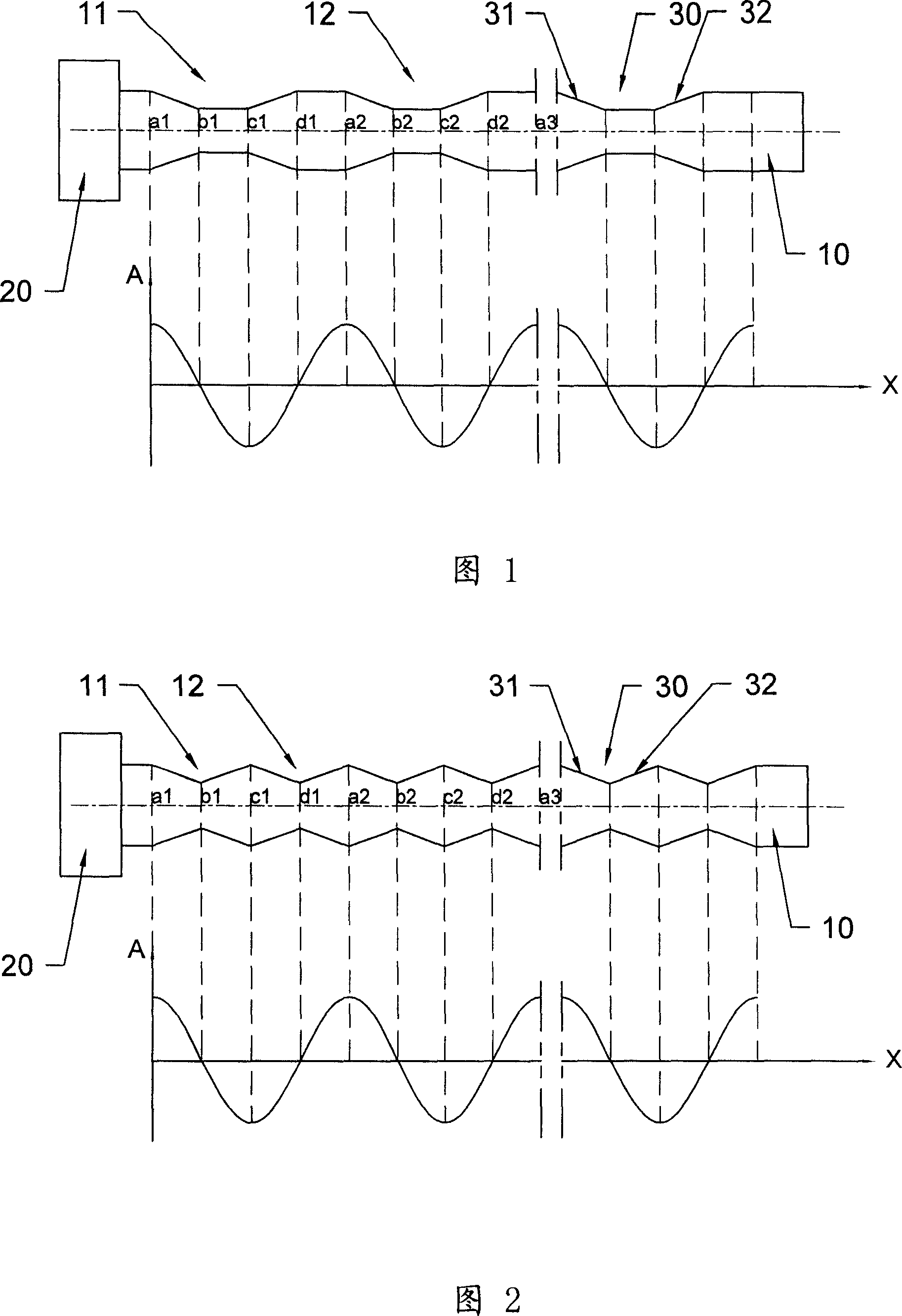
[0019] The upper part shown in FIG. 1 is a schematic structural diagram of the first embodiment of the ultrasonic radiator according to the present invention, and the lower part is a schematic diagram of amplitude distribution. As shown in the upper part of FIG. 1 , in the first embodiment of the ultrasonic radiator of the present invention, it includes a radiation rod 10 and a transducer 20 arranged at one end of the radiation rod 10 . Wherein, the transducer 20 can provide high-frequency mechanical vibration to the radiation rod 10 , and transducers can also be arranged at both ends of the radiation rod 10 . The cross-sectional shape of the radiation rod 10 can be circular, rectangular, and other shapes adapted to the shape of the elongated tube or the wall of the deep hole to be processed, and a plurality of annular grooves 30 are opened around the radiation rod 10, the The cross-sectional shape of the annular groove 30 is trapezoidal, including two annular radiating surfac...


PUM


Abstract

The invention relates to an ultrasonic wave radiator, comprising radiating rod with transducer at one end or two ends. Several ring grooves are set on the radiating rod. Said ring grooves comprise two faced ring radiating faces. When the rod generates vibration under the excitation of transducer these radiating faces can radiate ultrasonic wave. Because the radiating rod has many radiating faces the total radiating area of transducer is large and conversion efficiency from electricity to sound is high. Because the whole length direction of radiator can radiate ultrasonic wave treatment time can be shortened and working efficiency can be improved. By setting dimension and position of two faced radiating faces on said ring rod reasonably vibrations of two radiating faces are opposite phase in basic so that superposition sound field formed by ultrasonic wave radiated by two radiated faces is strengthened and the whole radiating effect is good.

Description

technical field [0001] The invention relates to other ultrasonic liquid treatment technologies such as ultrasonic cleaning and ultrasonic emulsification, and more specifically relates to an ultrasonic radiator for generating ultrasonic waves in liquid. Background technique [0002] At present, ultrasonic cleaning and other liquid treatment technologies have been widely used. It mainly produces high-frequency mechanical vibrations through transducers, and then radiates ultrasonic waves into the liquid to produce physical effects such as "cavitation" in the liquid, achieving For cleaning and disposal purposes of items. [0003] For the cleaning of slender tubes such as wine bottles and test tubes or the inner wall of deep holes, ultrasonic radiators are required to effectively transmit sound waves into the tubes or holes. At present, long longitudinal vibration rods are usually used as radiators, and only one end surface is used as the radiation surface, so the radiation area...

Claims


Application Information

Patent Timeline
Patent Type & Authority Applications(China)
IPC IPC(8): B06B1/00B06B3/00
Inventor 周光平梁召峰
Owner SHENZHEN POLYTECHNIC
Why Eureka
Try Eureka