Oscillating conveyer for cupola deslagging and deslagging method thereof

A vibrating conveyor and cupola technology, applied in vibrating conveyors, conveyors, transportation and packaging, etc., can solve the problems of low slag removal, dirty, no practical application value, etc., to ensure continuous operation and avoid waste Effect

Inactive Publication Date: 2008-01-02
天津勤美达工业有限公司
View PDF0 Cites 0 Cited by
  • Summary
  • Abstract
  • Description
  • Claims
  • Application Information

AI Technical Summary

Problems solved by technology

But the grab bucket is very inflexible, the efficiency is extremely low, and the slag removal is not clean, so it has no practical application value

Method used


Image

  • Oscillating conveyer for cupola deslagging and deslagging method thereof
  • Oscillating conveyer for cupola deslagging and deslagging method thereof
  • Oscillating conveyer for cupola deslagging and deslagging method thereof

Examples


Embodiment Construction

[0026] Below in conjunction with accompanying drawing and specific embodiment, vibrating conveyor for cupola slag removal of the present invention and its slag removal method are described in further detail:

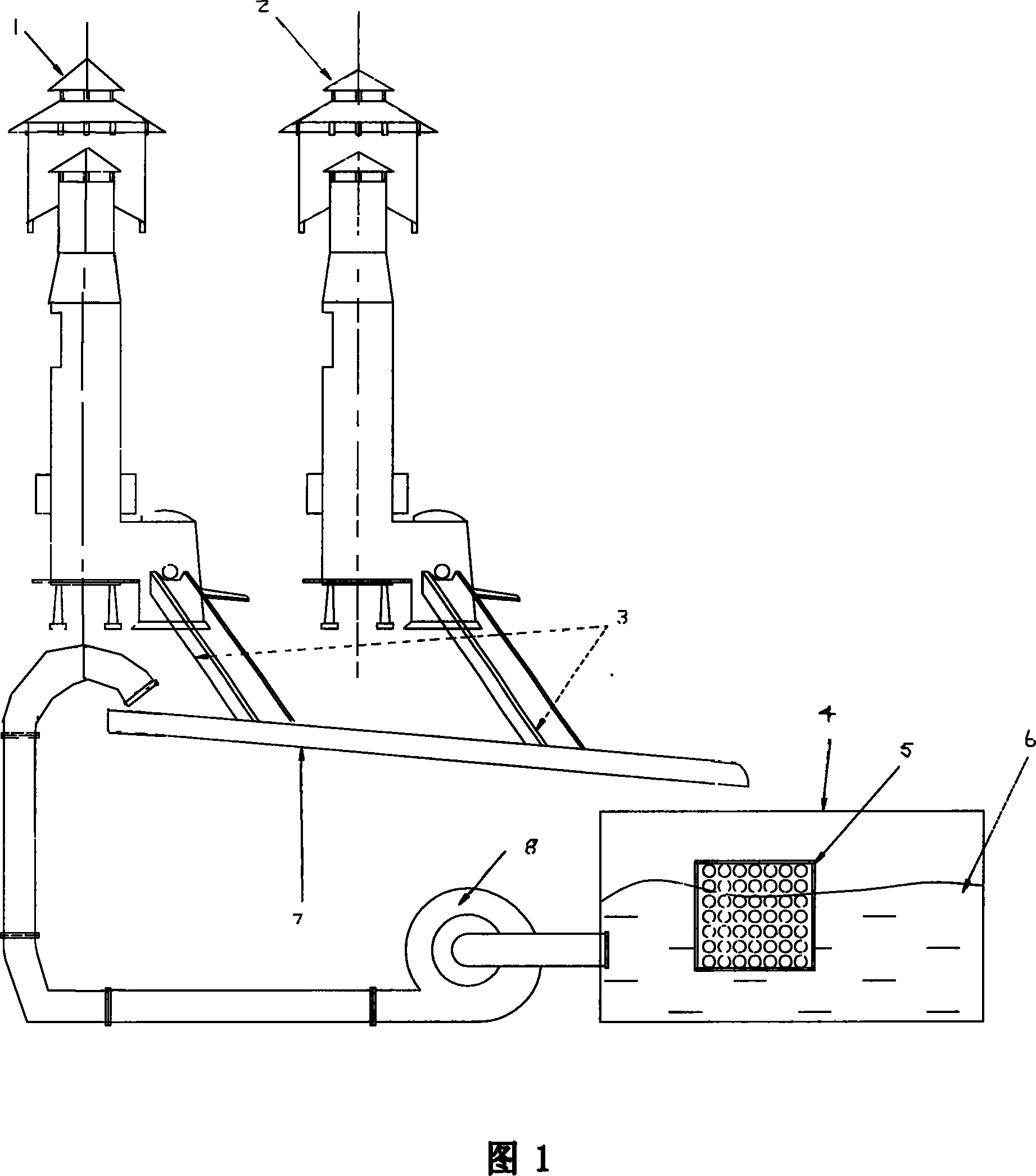
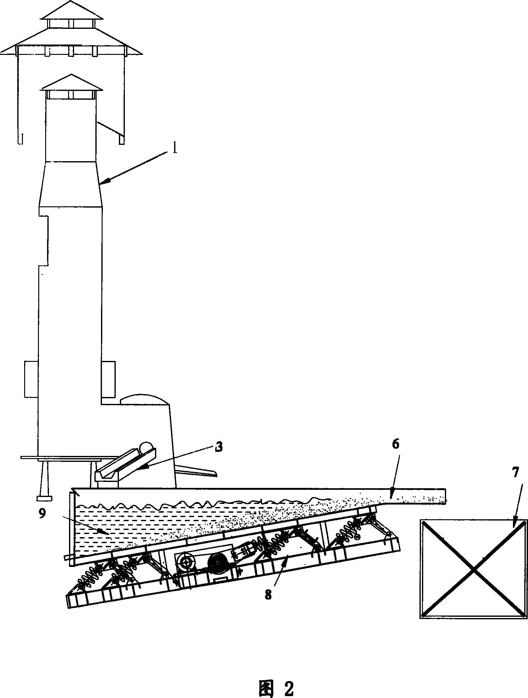
[0027] As shown in Fig. 2, the cupola 1 according to the present invention discharges the slag 6 into the deep part of the water 9 in the vibrating conveyor 8 through the slagging tank 3 for cooling.

[0028] The cooled slag 6 is discharged by the vibrating conveyor 8 and falls into the slag bucket 7, while the water 9 flows back to the vibrating conveyor 8 for recycling.

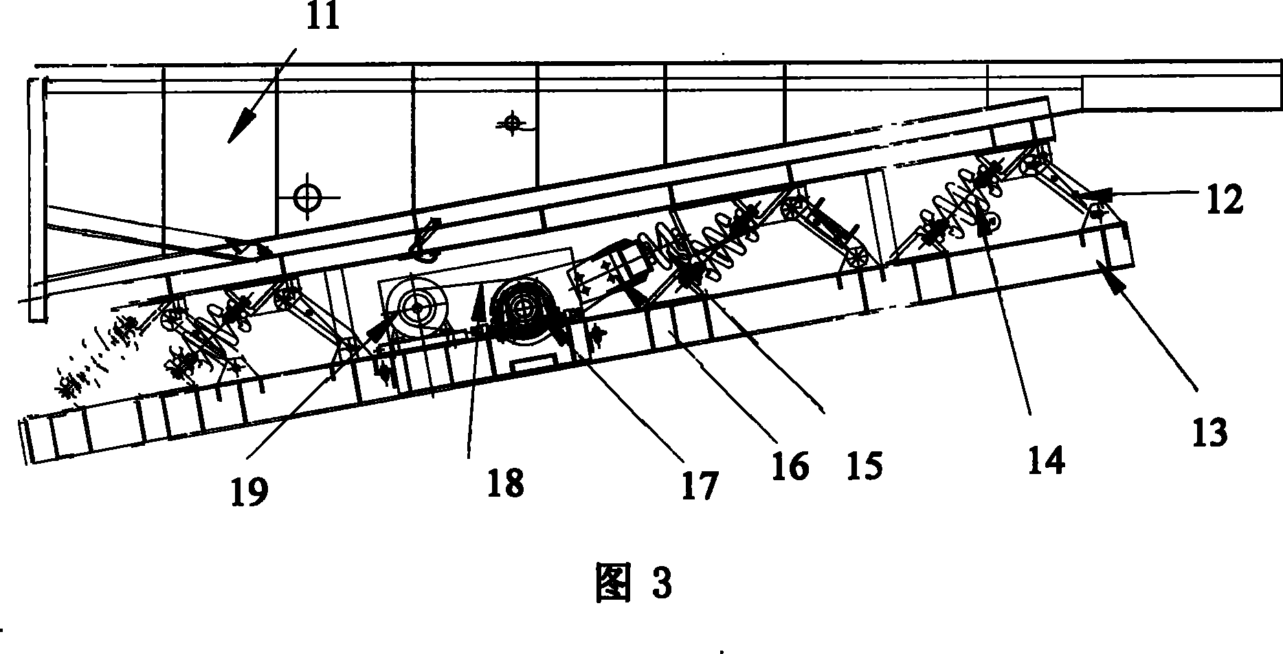
[0029] As shown in Figure 3, the vibrating conveyor 8 for cupola slag removal includes a slag water tank 11, a base 13, a movable connection device and a power unit, and the slag discharge tank 3 in the cupola 1 discharges the slag 6 to the slag water tank 11 Among them, the bottom surface of the slag water tank 11 is an inclined plane, and the longitudinal section of the slag water tank 11 is a right...


PUM


Abstract

The invention discloses an oscillating conveyer for removing the slag of the cupola, which comprises the following parts: a slag basin, a seat, a connecting device which can move and a power device, wherein the cupola discharges the furnace slag to the slag basin from the dirt-excluding groove, the bottom of the slag basin is oblique plane, the interior of the slag basin fills the water, the furnace slag can drop in the water depth, the bottom and the seat of the slag basin is parallel, the motion connecting device is connected with the slag basin and the seat separately and can produce the displacement between the slag basin and the seat, two ends of the power device are connected with the slag basin and the seat separately in order to provide the displacement power between the slag basin and the seat. The invention also discloses a method of the oscillating conveyer for removing the slag, which comprises the following steps: deepening the basin of the oscillating conveyer; forming the slag basin; putting the water for cooling the furnace slag in the slag basin. The invention changes the traditional cooling and collecting method.

Description

technical field [0001] The invention relates to a vibrating conveyor for slag removal in a cupola furnace and a slag removing method thereof, in particular to a vibrating conveyor for slag removal and a slag removing method for cooling and collecting slag during the melting process of a cupola furnace. Background technique [0002] The cupola of prior art, the mode melting molten iron of electric furnace duplex smelting. Two cupola furnaces are alternately repaired to ensure continuous supply of cupola molten iron. The slag is cooled and collected by placing net cages in the cooling water pool. As shown in Figure 1, due to the limitation of space, two cupolas share a slag removal pool. Because the net cage cannot completely separate the slag water, a small part of the slag always enters the slag pool, so the slag in the slag pool needs to be cleaned regularly, and the cupola needs to stop working during the cleaning, so that the continuous supply of molten iron in the cupo...

Claims


Application Information

Patent Timeline
Patent Type & Authority Applications(China)
IPC IPC(8): C21B3/06B65G27/10
CPCY02W30/50
Inventor 林政德
Owner 天津勤美达工业有限公司
Why Eureka
Try Eureka