

Welding structural body
A technology for structural bodies and welding parts, which is applied in the direction of connecting components, welding equipment, thin plate connections, etc., can solve problems such as high cost, and achieve the effect of simple processing and simple composition
- Summary
- Abstract
- Description
- Claims
- Application Information
AI Technical Summary
Problems solved by technology
Method used
Image

Examples
no. 1 Embodiment approach
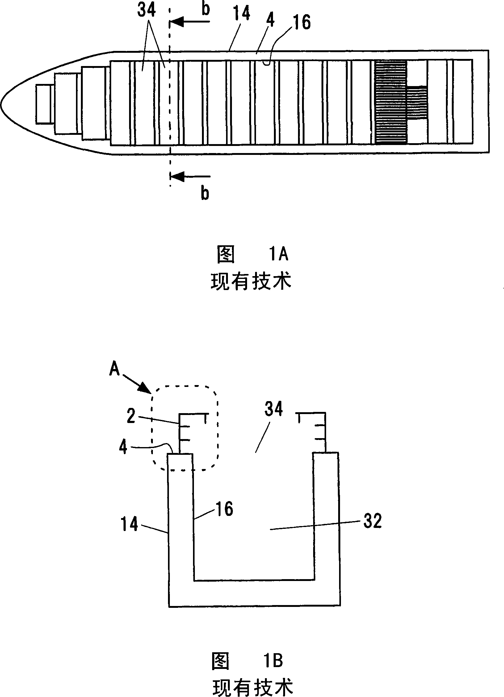
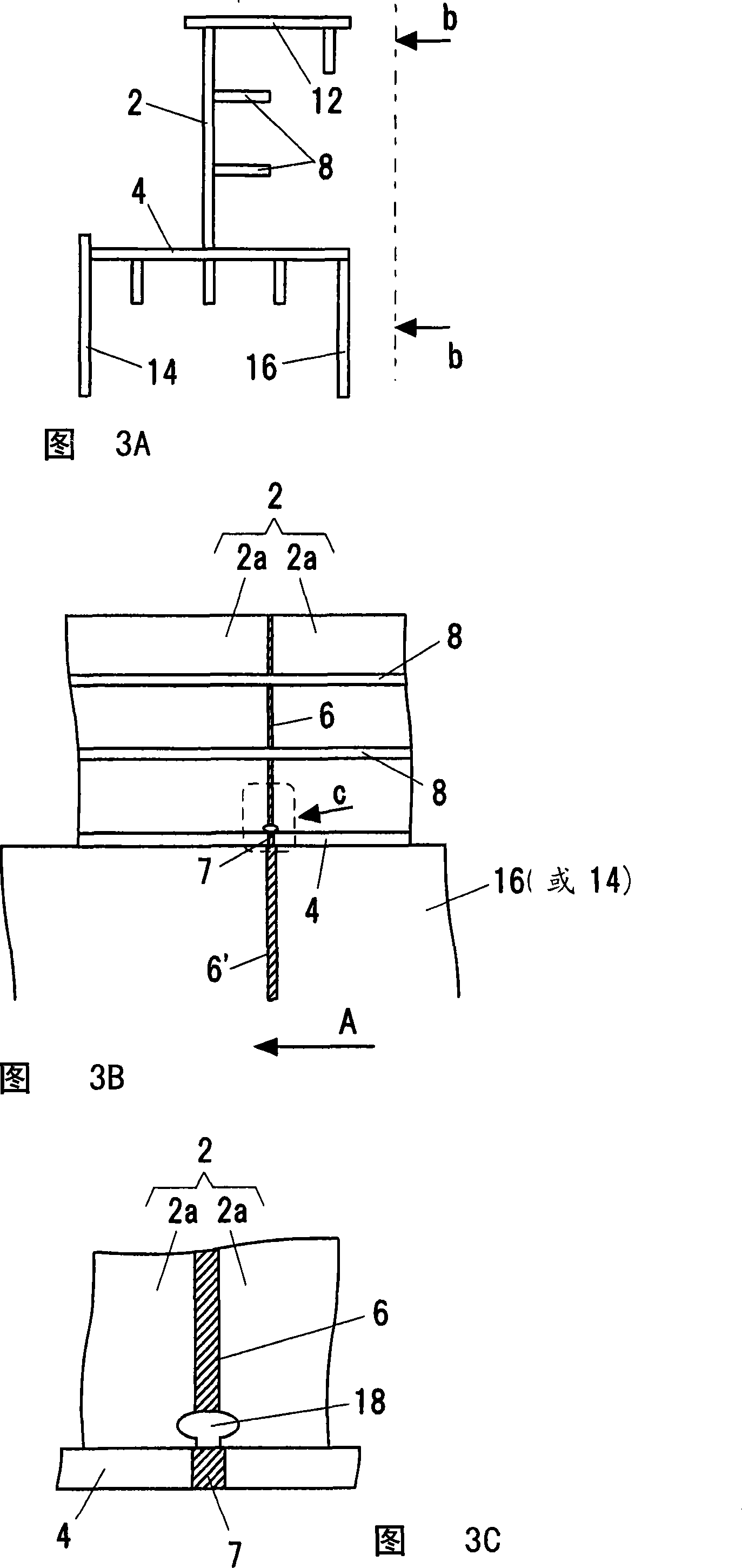
[0066] Fig. 3A is an enlarged view of the part indicated by the arrow A in Fig. 1B, showing the application of the welded structure according to the first embodiment of the present invention (corresponding to the first invention) to the hatch coaming and upper deck of the container ship Case.
[0067] As shown in FIG. 3A , the welded structure of the first embodiment is a structure in which a hatch coaming 2 is welded to an upper deck 4 .
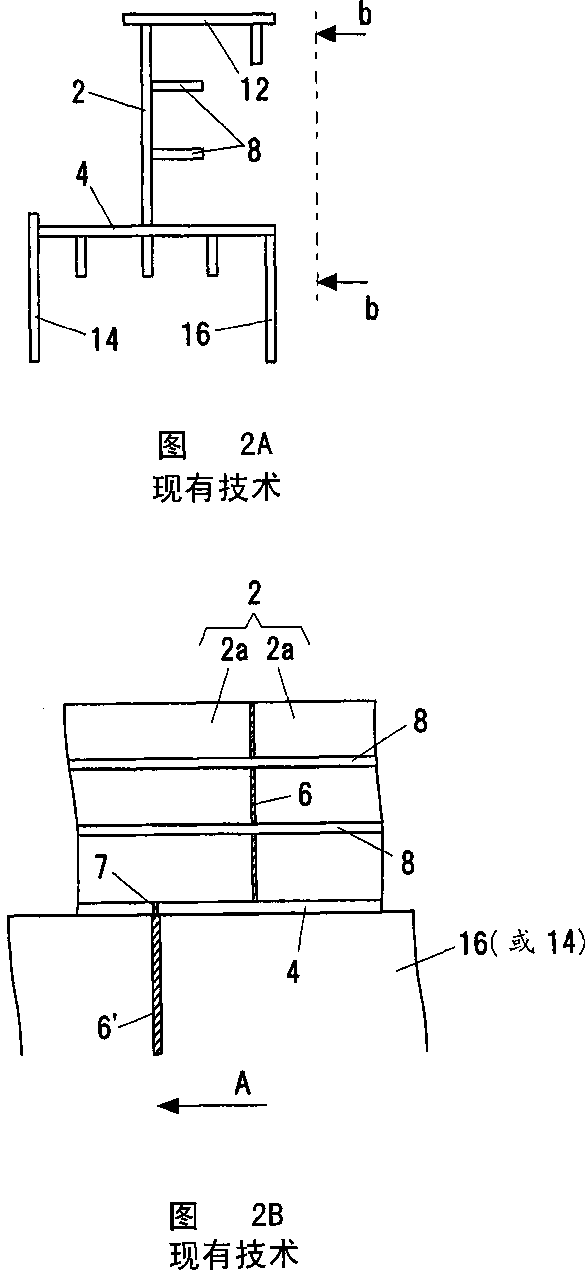
[0068] Fig. 3B is a view in the direction of arrow b-b line in Fig. 3A. As shown in FIG. 3B , the hatch coaming 2 is formed by welding two or more metal plates 2 a (in this example, steel plates) to butt their end faces together. In addition, a bone member (aggregate) 8 as a reinforcement member extending in a direction perpendicular to the welded joint portion 6 is joined to the side surface of the hatch coaming 2 by fillet welding. In addition, a top plate 12 arranged in the horizontal direction is welded to the upper end of the hatch c...
no. 2 Embodiment approach
[0084] Next, a welded structure according to a second embodiment of the present invention will be described. Configurations other than those described below may be the same as those of the first embodiment.
[0085] FIG. 6A is an enlarged view of a portion indicated by arrow C in FIG. 3B , showing a welded structure according to a second embodiment. In addition, FIG. 6B is a view in the direction of the arrow b-b line in FIG. 6A .
[0086] As shown in FIGS. 6A and 6B , near the joint position of the welded joint portion 6 and the upper deck 4 , a contact prevention member 28 is sandwiched between the welded joint portion 6 and the upper deck 4 so that the welded joint portion 6 does not come into contact with each other. Go to upper deck 4. The contact protection member 28 can be formed, for example, from relatively tough mild steel. In addition, the shape of the contact preventing member 28 may be a flat plate shape in which the corners of the four corners of the upper sur...
no. 3 Embodiment approach
[0099] Fig. 9A is a view in the direction of the arrow b-b line in Fig. 3A, showing the application of the welded structure according to the third embodiment (corresponding to the second technical solution) of the present invention to the hatch coaming of a container ship. As shown in FIG. 9A , the welded structure according to the third embodiment includes a structure in which two or more metal plates 2 a (in this example, steel plates) are butted against each other and welded together.
[0100] Fig. 9B is an enlarged view of a portion indicated by arrow b in Fig. 9A. As shown in FIG. 9B , according to the third embodiment, a hole 29 is formed through the welded joint 6 in the thickness direction of the hatch coaming 2 so that the welded joint 6 extending between the two metal plates 2 a Disconnected midway.
[0101] In this way, in the welded structure according to the third embodiment, since the hole 29 penetrating the welded joint 6 is provided, there is no brittle crack ...
PUM
 Abstract
Description
Claims
Application Information