Bearing channel automatic sorting machine
An automatic sorting and bearing channel technology, applied in sorting and other directions, can solve the problems of large changes in sorting accuracy and efficiency, and achieve the effect of high speed and high precision
- Summary
- Abstract
- Description
- Claims
- Application Information
AI Technical Summary
Problems solved by technology
Method used
Image
Examples
Embodiment 1
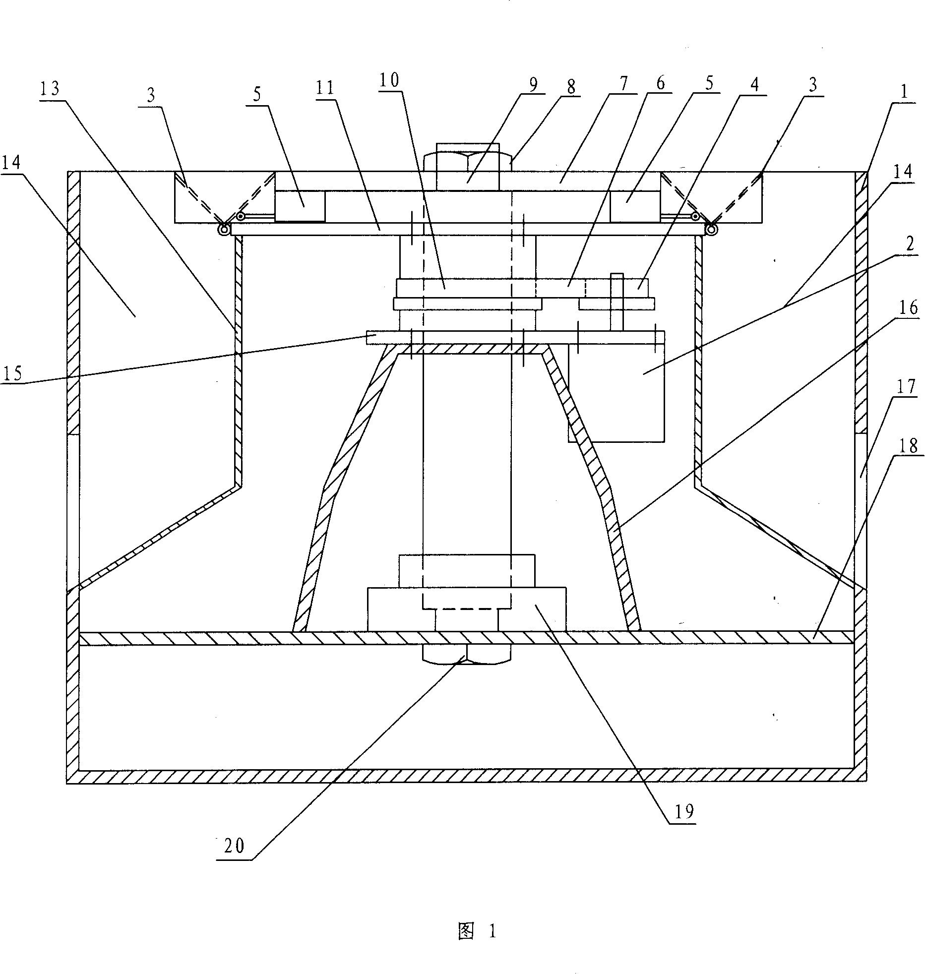
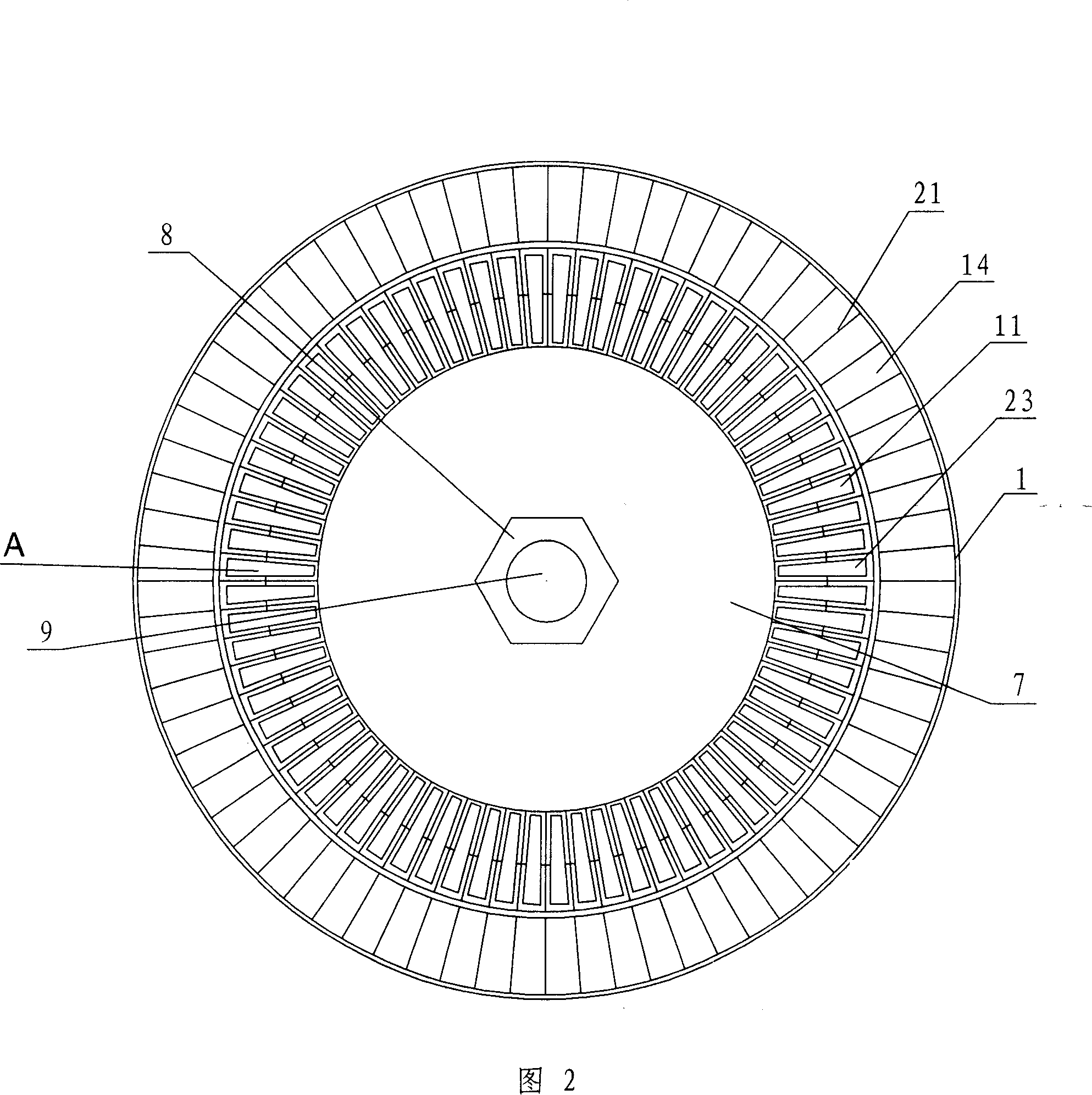
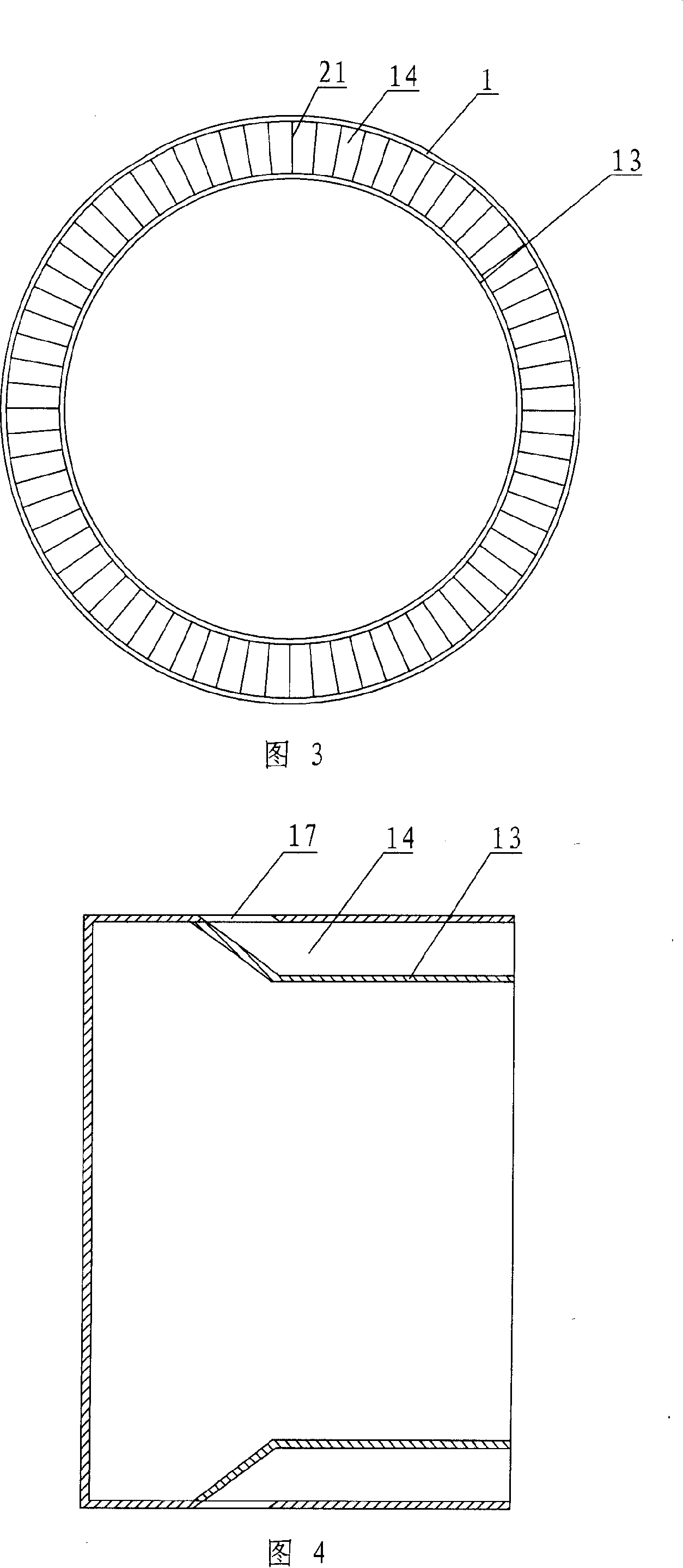
[0020] The automatic sorting machine for bearing grooves is composed of a central shaft 9, a driving mechanism 15, and a frame 1 with a sorting slideway 14. The frame 1 is fixed with a beam 18 and a lower bracket 16, and the central shaft 9 passes through The lower bracket 16 is placed in the base 19 and fixed on the crossbeam 18 by a fastener 20, the driving mechanism 15 is fixed on the lower bracket 16, and the central shaft 9 A rotary transmission mechanism 11 is installed on it, and a platform 7 is fixed on the top of the central axis 9. The sorting slideway 14 on the frame 1 is aligned with the material channel 23 on the rotary transmission mechanism, and the sorting slideway 14 is formed by sorting The slideway dividing plate 21 and the slideway plate 13 constitute. The drive mechanism 15 includes a drive motor 2, the drive motor 2 is fixed on the motor support 25 by a fastener, and the motor support 25 is fixed on the lower bracket 16 by a fastener, The motor shaft of ...
Embodiment 2
[0022] In the above-mentioned automatic sorting machine for bearing channels, the platform 7 is fixed on the central shaft 9 through a fastener 8, and an unloader 5 is installed under the platform 7 through a fastener. Devices 5 correspond to the dump buckets 3 on the rotary transmission mechanism 11 respectively. The rotary transmission mechanism of the present invention is composed of a material channel plate 26, a dividing plate 27, and a passive toothed wheel 10. The material channel plate 26 is provided with a dividing plate 27, and the gap between the dividing plate 27 and the dividing plate 27 The forehearth 29 formed between, the outer diameter of the forehearth plate 26 is fixed with a seat ear 28, the seat ear 28 is installed with a tipping bucket 3, the bottom of the forehearth plate 26 is fixed with a passive tooth through a fastener 32 shaped wheel 10. The dump bucket 3 is arranged in the material channel 29 .
[0023] Description of working process:
[0024] T...
PUM
 Abstract
Description
Claims
Application Information
 - R&D
- Intellectual Property
- Life Sciences
- Materials
- Tech Scout
- Unparalleled Data Quality
- Higher Quality Content
- 60% Fewer Hallucinations
Browse by: Latest US Patents, China's latest patents, Technical Efficacy Thesaurus, Application Domain, Technology Topic, Popular Technical Reports.
© 2025 PatSnap. All rights reserved.Legal|Privacy policy|Modern Slavery Act Transparency Statement|Sitemap|About US| Contact US: help@patsnap.com


