Depth tracking device for logging while drilling

A logging-while-drilling, depth-tracking technology, applied in surveying, earth-moving, wellbore/well components, etc., can solve the problems of no depth sensor installed in place, inability to collect depth signals, and steel cable slippage, etc., to achieve maintenance and supply. The effect of fast delivery, accurate tracking and low cost

Active Publication Date: 2008-01-09
CHINA NAT OFFSHORE OIL CORP +1
View PDF0 Cites 8 Cited by
  • Summary
  • Abstract
  • Description
  • Claims
  • Application Information

AI Technical Summary

Problems solved by technology

[0002] At present, the depth system of logging while drilling needs to install the depth sensor on the rotating shaft of the drilling winch. The new digital offshore drilling platform HY-941 adopts a fully enclosed drilling winch system, and there is no place to

Method used


Image

  • Depth tracking device for logging while drilling

Examples


Example Embodiment

[0017] In order to detect without using a depth sensor, it is necessary to use the hook height signal output by the electronic driller system of the offshore oil drilling platform. The hook height signal is a 4-20 mA current signal. Therefore, it is necessary to design a set of devices to convert this height signal into a speed signal that can be identified by the logging while drilling depth system.

[0018] Hereinafter, the depth tracking device along with drilling of the present invention will be described in detail with reference to the accompanying drawings.
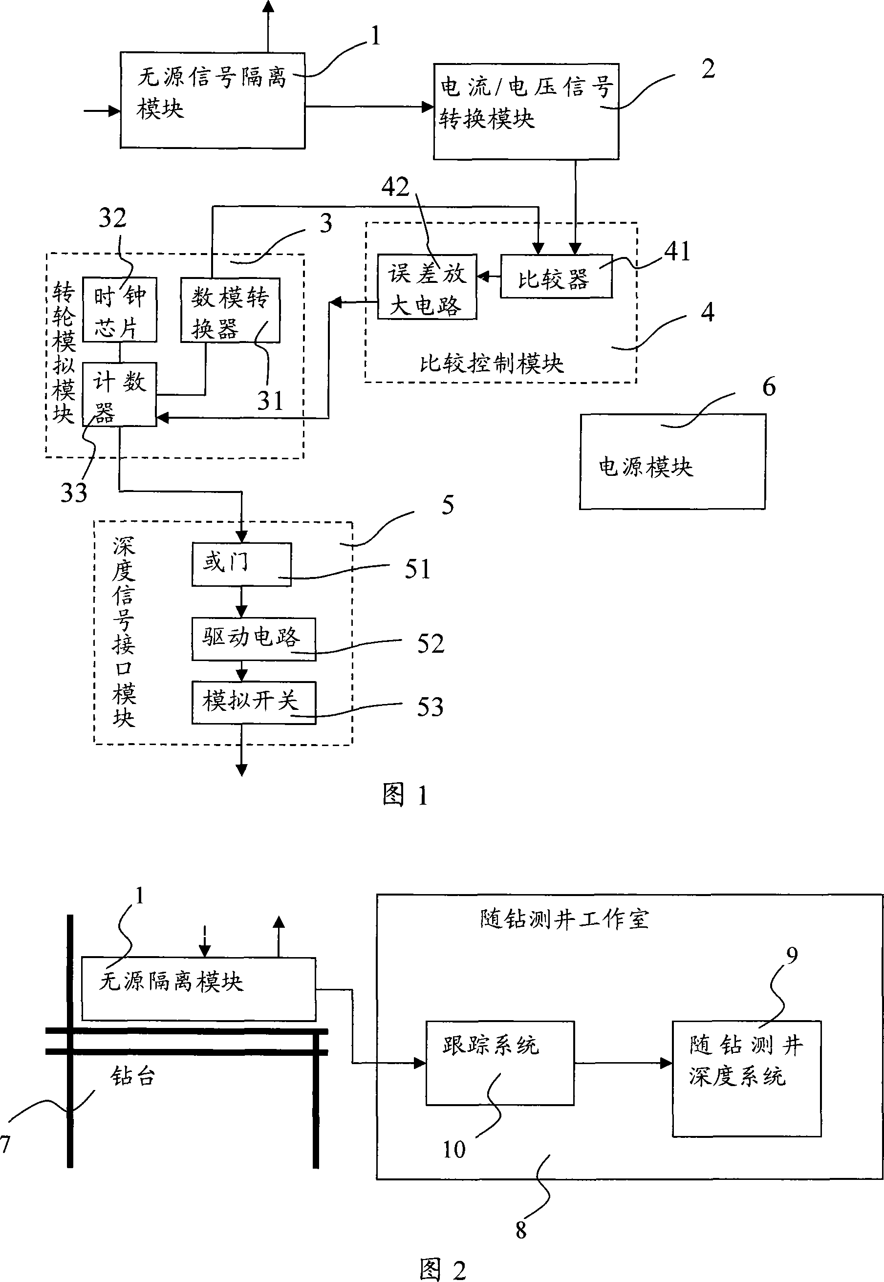
[0019] As shown in FIG. 1, the present invention includes: a passive signal isolation module 1, a current / voltage signal conversion module 2, a runner simulation module 3, a comparison control module 4, a depth signal interface module 5 and a power supply module 6.

[0020] The passive signal isolation module 1 converts the 4-20mA signal of the hook height output by the electronic driller system of the offshore oil dril...


PUM


Abstract

A tracing device along with drilling includes current/voltage signal transfer module, motor simulation module, comparison control module, depth signal module and power source module. With this invention, it is not necessary to install a depth sensor to winch and the related mechanical transition. All signals are electronically transferred and treated.

Description

technical field [0001] The invention relates to a tracking device for logging-while-drilling depth on a drilling platform. Background technique [0002] At present, the depth system of logging while drilling needs to install the depth sensor on the rotating shaft of the drilling winch. The new digital offshore drilling platform HY-941 adopts a fully enclosed drilling winch system, and there is no place to install the depth sensor. The current logging while drilling Depth sensors cannot collect depth signals on such platforms. Moreover, the current depth sensor is rotated by the steel cable with the runner, and sometimes the steel cable slips, causing depth errors. Contents of the invention [0003] The technical problem to be solved by the present invention is to provide a logging-while-drilling depth tracking device that can be independently applied to drilling platforms. [0004] A logging-while-drilling depth tracking device of the present invention includes: a curren...

Claims


Application Information

Patent Timeline
IPC IPC(8): E21B47/04
Inventor 吴兴方林长浓陈秋炎刘国武朱江梅廖运荣邵丰孙学雷肖刚
Owner CHINA NAT OFFSHORE OIL CORP
Why Eureka
Try Eureka