Driving roller for belt line

A technology for driving rollers and wires, applied in the field of roller friction, can solve the problems of reducing the service life of the track, increasing the labor time of workers, delaying the processing efficiency of products, etc., to achieve the effect of enhancing processing efficiency, reducing working time of employees, and increasing tightness

Inactive Publication Date: 2021-04-13
南通利俊自动化设备有限公司
View PDF9 Cites 3 Cited by
  • Summary
  • Abstract
  • Description
  • Claims
  • Application Information

AI Technical Summary

Problems solved by technology

[0004] 1. When the existing roller is rotating and transporting, the degree of friction between the outer surface and the track will increase with the use time, and the pattern on the surface will be worn off, which will cause the track to slip on the surface of the roller, thereby affecting The problem of delaying the processing efficiency of the product and increasing the labor time of workers due to the normal use of the crawler instrument roller;
[0005] 2. When the existing roller is working, there will be a lot of high temperature between the track and the roller. In the high temperature environment, there will be a thermal expansion reaction between the track and the roller, which will reduce the performance of the track under long-term use. service life

Method used


Image

  • Driving roller for belt line
  • Driving roller for belt line
  • Driving roller for belt line

Examples


Embodiment 1

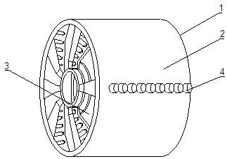
[0045]Such asFigure 1-10As shown, the present invention provides a belt wire drive drum including a drive drum body 1, and the drive drum body 1 includes a foreign shield 2, and the outer sheave 2 is provided with a cooling device 3, and the cooling device 3 includes a ring 31. The outer surface of the outer cover 2 is fixedly connected to the damper 4, and the damper column 4 includes a U-shaped sleeve 41.

[0046]In the present embodiment, the temperature of the outer retaining ring 2 is lowered by the cooling device 3 to reach the high temperature environment between the alleviated outer sheath 2 and the track, and the shock absorbing column 4 increases friction between the track and the outer sheath 2. Force, increase the use of strip floral on the surface of the track.

[0047]Such asFigure 1-10As shown in the present embodiment, it is preferable that the friction layer 45 includes a guard 451, and a fixed block is fixedly connected to the outer surface of the guard plate 451, and th...

Embodiment 2

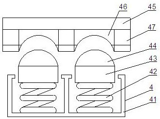
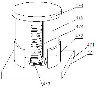
[0050]Such asFigure 1-10As shown in the basis of the first embodiment, the present invention provides a technical solution: preferably, the inner surface of the U-shaped sleeve 41 is fixedly coupled to the spring 122, and the spring 1 42 is fixedly connected to the haterflainer 43. The outer surface of the haterflower 43 is fixed to the outer surface of the thermal conductive layer 44, and the outer surface of the heat conductive layer 44 is attached to the outer surface of the internal arc block 46, and the friction layer 45 is fixedly connected. The exterior surface is fixedly connected to the damper spring 47, by providing the inner arc block 46 on the outer surface of the friction layer 45, and then connect the heat conductive layer 44 inside the damper 4 and the inner arc block during rotation. 46 will generate a pressure on the thermally conductive layer 44, and use the spring 42 to reverse the internal arc block 46 to increase the tightness between the two, and then use the c...

Embodiment 3

[0052]Such asFigure 1-10As shown, in the basis of the first embodiment, the present invention provides a technical solution: preferably, the inner surface of the retaining ring 31 is fixedly connected to the water pipe 32, and the outer surface of the water pipe 32 is provided with waterproof rubber blocks 33, and the water pipe 32 The surface is fixedly connected to the surface of the water absorbing roller 34, and the water pipe 35 is fixed to the outer surface of the ladle 31, and the water pipe 32 includes a water tube 321, the outer surface of the sheath 31. The inner surface of the connecting hole 322 and the inner surface of the water tube 321 is provided on the upper surface, and the drain port 324 is provided on one end of the water tank 323, and the water source is performed through the water tube 323, and then the water source is directed to the water source. On the surface of the connecting hole 322, the internal water source is guided by the water guide roller 34, and t...


PUM


Abstract

The invention discloses a driving roller for a belt line, and relates to the technical field of roller friction. The driving roller for the belt line comprises a driving roller body, wherein the driving roller body comprises an outer protective ring; a cooler is arranged in the outer protective ring, and comprises a protective ring; damping columns are fixedly connected onto the outer surface of the outer protective ring in a covering manner; the damping columns comprises U-shaped sleeves; first springs are fixedly connected onto the inner surfaces of the U-shaped sleeves; air suction devices are fixedly connected onto one ends of the first springs; heat conduction layers are fixedly connected onto the outer surfaces of the air suction devices; and inner arc blocks are connected onto the outer surfaces of the heat conduction layers in a lap joint mode. According to the driving roller for the belt line provided by the invention, friction force with the roller is increased through an inner friction layer, and strip-shaped patterns on the surface are increased through strip-shaped lines on the surface of an outer protective layer, so that friction force with an external object is increased; and pressure resistance of the strip-shaped lines is improved through tension springs in the strip-shaped lines, so that the effects of realizing pressure resistance on the patterns on the surface, and reducing the pattern abrasion degree are achieved.

Description

Technical field[0001]The present invention relates to a drive drum device, and the field of roller friction, and more particularly to a belt wire drive drum.Background technique[0002]Roller, cylindrical parts, are divided into drivers and driven rollers, applied to various types of transmission transport systems such as printing machines, digital printers, etc., parallel steel, cast steel, forged metal steel Core is material.[0003]There is the following problems for the prior art:[0004]1. When the existing roller is rotating, the friction between the outer surface and the track will be grinded as the use time increases, the pattern on the surface will be worn away, resulting in slipping on the surface of the drum, which in turn To the normal use of the crawler roller, delay the processing efficiency of the product, increase the problem of workers' labor time;[0005]2. When the existing drum is working, there is a large number of high temperature situations between the track and the r...

Claims


Application Information

Patent Timeline
Patent Type & Authority Applications(China)
IPC IPC(8): B65G23/04B65G39/06B65G39/10F25D31/00
CPCB65G23/04B65G39/06B65G39/10F25D31/00
Inventor 孙嘉慧孙俊林孙浩伟吴晓濛赵建平
Owner 南通利俊自动化设备有限公司
Why Eureka
Try Eureka