
Exterior structure of apparatus and image forming apparatus using the same

一种图象、外形的技术,应用在应用电荷图形的电记录工艺的设备、应用电荷图形的电记录工艺、仪器等方向,能够解决装置变大、外装结构复杂等问题,达到布局容易、提高作业性、简单布置的效果

Inactive Publication Date: 2008-01-09
SHARP KK
View PDF1 Cites 1 Cited by
  • Summary
  • Abstract
  • Description
  • Claims
  • Application Information

AI Technical Summary

Problems solved by technology

[0006] However, when there are multiple heat sources and scattering sources inside the device, each source should be connected to a pipe in order to discharge and transfer heat and collect pollutant particles, so this structure will make the device larger, and due to the arrangement of the pipes will make the exterior structure more complicated

Method used


Image

  • Exterior structure of apparatus and image forming apparatus using the same
  • Exterior structure of apparatus and image forming apparatus using the same
  • Exterior structure of apparatus and image forming apparatus using the same

Examples


no. 1 example

[0054] Now, an embodiment of the present invention will be described in detail with reference to the accompanying drawings.

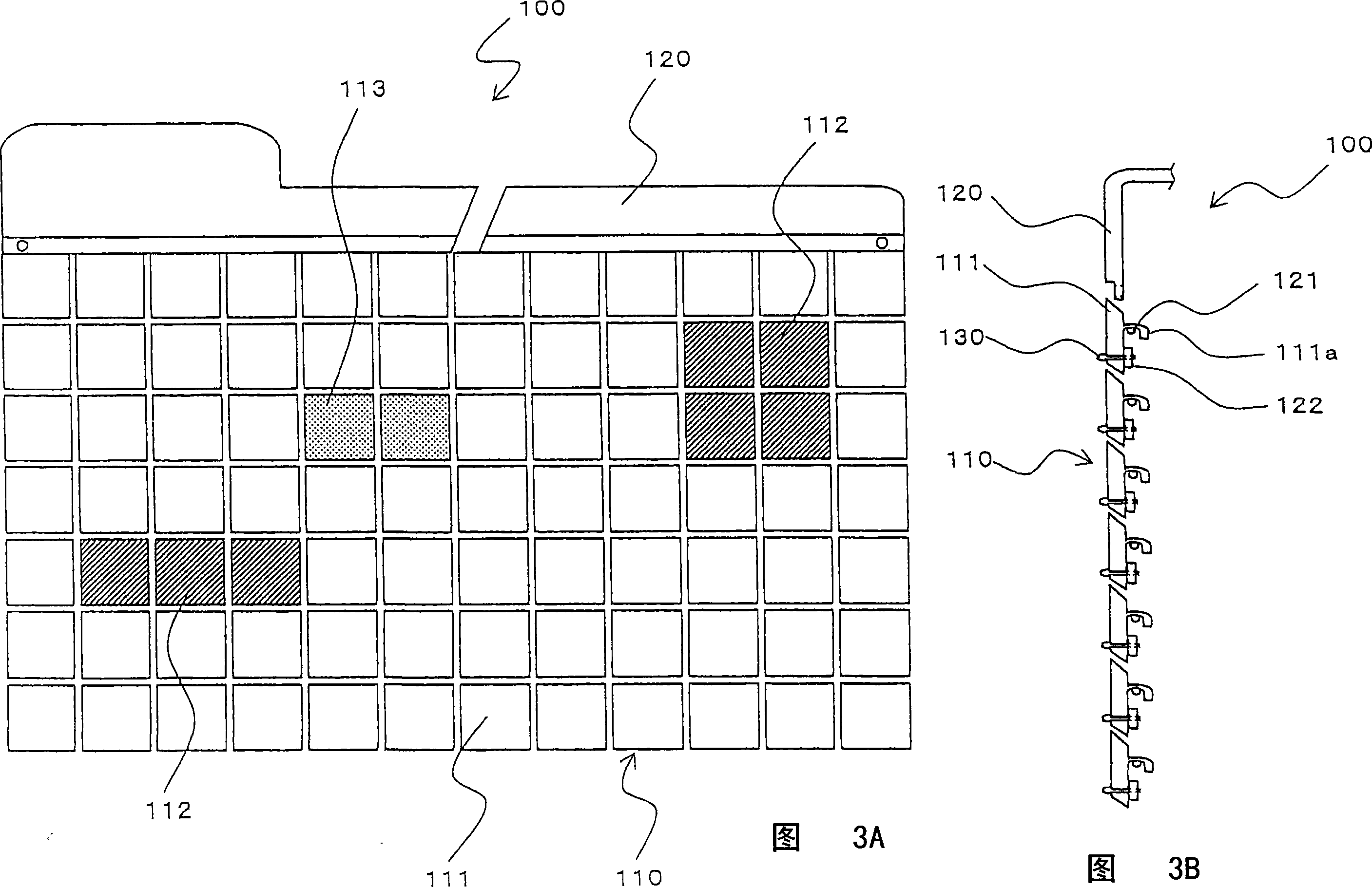
[0055] Figures 3-5 show a pattern of the embodiment of the present invention. FIG. 3A is a schematic diagram of the form of the exterior structure of the device according to the first embodiment of the present invention, and FIG. 3B is a side view of the form of the exterior structure. Fig. 4 is an explanatory view of the form of the panel element constituting the exterior structure, Figs. 4A and 4D are side views of the protective panel form, Figs. 4B and 4E are the side views of the heat dissipation panel form, and Figs. 4C and 4F are the anti-scattering panels inside the machine Side view of the morphology. Fig. 5 is a partial explanatory view of the form of the frame constituting the exterior structure.

[0056] The exterior structure 100 of the main device of this embodiment includes a plurality of separate panel elements 110 and a frame 120, as shown ...

no. 2 example

[0107] Next, the image forming apparatus 1A (FIG. 13) including the transfer device 10 of the present invention will be described with reference to the drawings.

[0108] 13 is an explanatory view of the overall structure of an image forming apparatus adopting an exterior structure according to a second embodiment of the present invention; FIG. 14 is a partial detailed view of the main structure of the image forming apparatus.

[0109] The image forming apparatus 1A according to this embodiment includes an image forming section 14, a transfer device 10, a fixing unit (fixing mechanism) 6, and a conveying system, and generates an image output corresponding to a print request. As the exterior structure covering the exterior of the main body of the image forming apparatus, the exterior structure of the apparatus according to the present invention is adopted.

[0110] The image forming section 14 includes a photosensitive drum (electrostatic latent image carrier) 3, and a developer im...


PUM


Abstract

An exterior structure of an apparatus for covering the outside of an apparatus main body with a multiple number of panel elements uses shielding panels, heat-radiating panels and machine-interior anti-scatter panels as the multiple number of panel elements. The apparatus has a framework to which shielding panels, heat-radiating panels and machine-interior anti-scatter panels are appropriately arranged in combination to cover the apparatus in conformity with the functional configuration of the apparatus.

Description

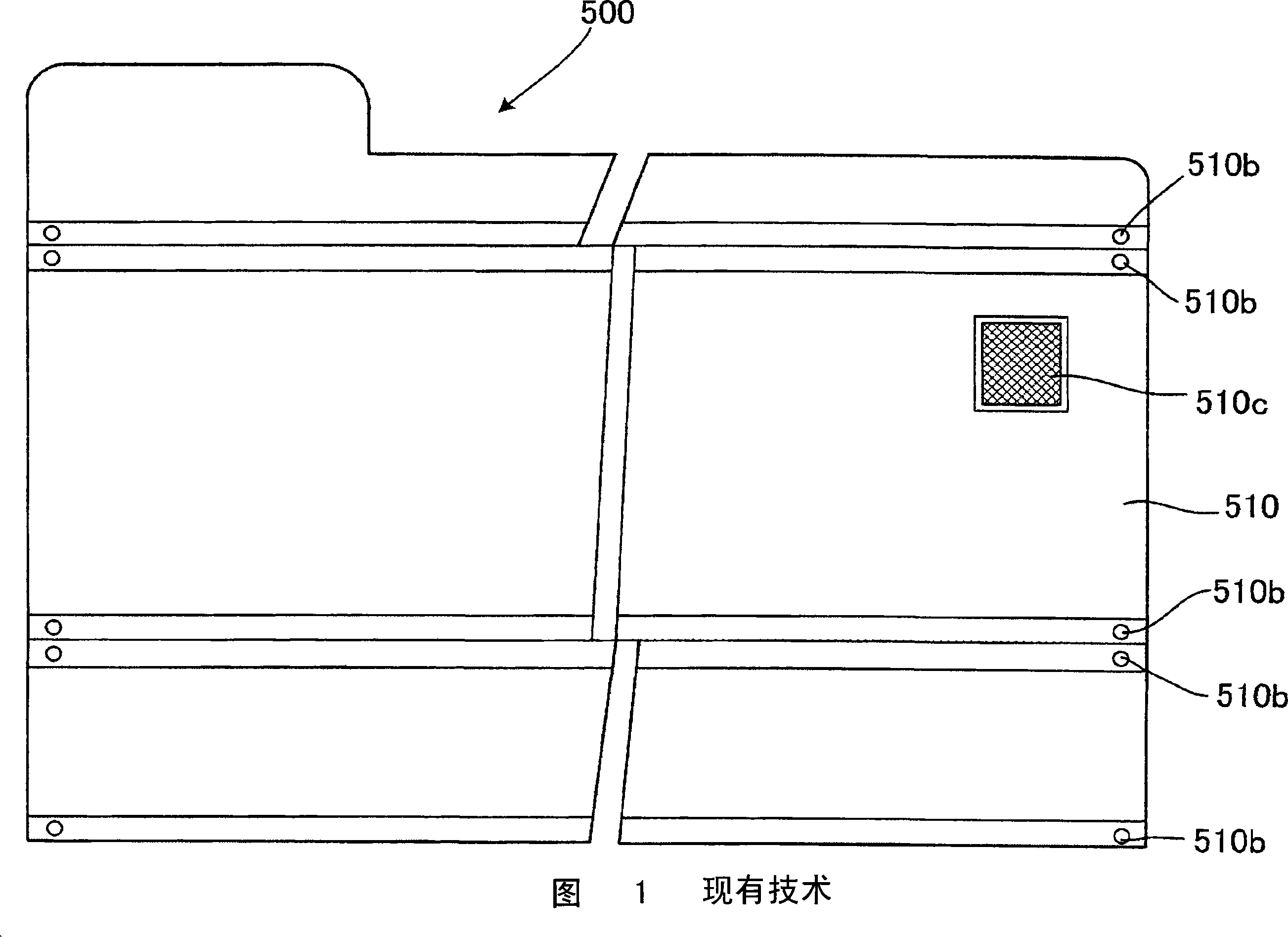
Technical field [0001] The present invention relates to an exterior structure of a device and an image forming apparatus adopting such exterior structure. In particular, the present invention relates to an exterior package for ventilation of a device having a drive unit and a heat source and heat dissipation of heat accumulated in the device Structure, and an image forming apparatus adopting the exterior structure. Background technique [0002] One purpose of the exterior structure of the device is to prevent users from directly contacting the drive components, heat sources and other internal components of the device, and to pursue the aesthetics of the device's appearance and the improvement of its functions. [0003] As a well-known device exterior structure, there is an exterior structure 500 for a document reader, as shown in FIGS. 1 and 2, for example, a single-plate-shaped member 510 is fixed to the device frame by screws or other fixing methods ( Not shown) on. In the figu...

Claims


Application Information

Patent Timeline
Patent Type & Authority Applications(China)
IPC IPC(8): G03G15/00G03G21/00
CPCG03G2221/1678G03G21/1619G03G21/16
Inventor 长尾裕之菊谷孝史米田和久中村泰北浦敏一万代英伸
Owner SHARP KK
Learn More