A mixing motion detection method combining with video encoder

A video encoder and hybrid motion technology, applied in digital video signal modification, television, instrument, etc., can solve the problem of high computational complexity, achieve the effect of small data calculation and reduce hardware cost

Inactive Publication Date: 2008-01-09
ZTE CORP
View PDF0 Cites 8 Cited by
  • Summary
  • Abstract
  • Description
  • Claims
  • Application Information

AI Technical Summary

Problems solved by technology

[0006] The purpose of the present invention is to address the defects in the prior art, to provide a method for obtaining the final motion information by combining the motion vector information obtained by the video encoder with the improved frame difference method, and to overcome the complicated calculation of the existing motion detection method Disadvantages of too high degrees, and a good reduction of false positives and false negatives

Method used


Image

  • A mixing motion detection method combining with video encoder
  • A mixing motion detection method combining with video encoder
  • A mixing motion detection method combining with video encoder

Examples


Embodiment Construction

[0025] Various preferred embodiments of the present invention will be described in more detail below in conjunction with the accompanying drawings.

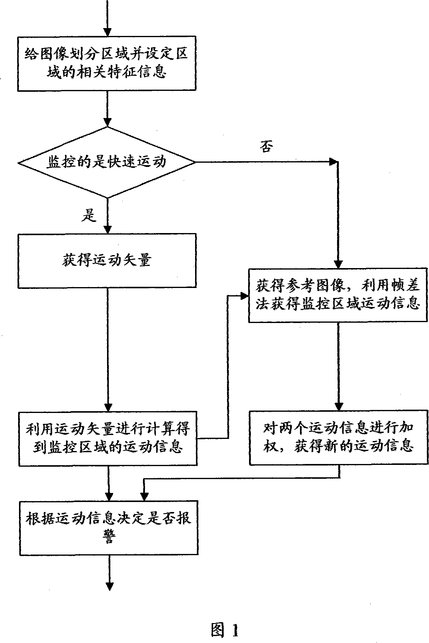
[0026] The hybrid motion detection method in conjunction with video encoder of the present invention, as shown in Figure 1, it comprises the steps:

[0027] The first step is to divide the image of the video surveillance area into several areas and set the relevant feature information in the area. The division of this area is determined by the application program, such as by artificially demarcating the range of the area to be monitored, and the number of areas to be monitored. These areas can be overlapped; the motion feature information includes: thresholds of various monitoring parameters, such as motion information thresholds, including monitoring slow targets, fast targets, or targets exceeding a specific speed, etc.;

[0028] The second step is to judge whether it is monitoring fast motion, and if so, obtain the motion vect...


PUM


Abstract

The method comprises: partitioning the image of monitored area into several areas, setting up the correlative feature information about the set areas; said feature information comprise: the motion information threshold, and the monitored low speed target, high speed target and target over a defined speed; getting the motion vector from video encoder, and getting the motion information about the monitored area; comparing the obtained motion information with the preset motion information threshold to determine the final motion information; reporting the final motion information.

Description

technical field [0001] The invention relates to a network video monitoring method, in particular to a method for hybrid motion detection combined with a motion vector (MV: motion veter) of a video encoder and a frame difference method. Background technique [0002] Common motion detection methods in the prior art include: frame difference method (including background subtraction method and time difference method), motion vector method and so on. The so-called background subtraction method is a technology that uses the difference between the current image and the background image to detect the moving area. sensitive. [0003] The so-called time difference method is to use pixel-based time difference and thresholding between two or three adjacent frames in a continuous image sequence to extract the moving area in the image. The temporal difference motion detection method has strong adaptability to the dynamic environment, but generally cannot fully extract all the relevant f...

Claims


Application Information

Patent Timeline
Patent Type & Authority Applications(China)
IPC IPC(8): H04N7/36H04N7/32G06T7/20G08B13/196H04N19/503H04N19/513
Inventor 刘帅陈军刘军莉佟鑫张良平
Owner ZTE CORP
Why Eureka
Try Eureka