Distortion correcting device of X-ray image tube

A distortion correction and kinescope technology, applied in the direction of image conversion/image amplification tube, screen tube, eliminating unnecessary electromagnetic effects, etc., can solve the problem of not being able to detect external magnetic fields, and achieve the effect of correcting distortion

Inactive Publication Date: 2008-01-09
KK TOSHIBA +1
View PDF2 Cites 3 Cited by
  • Summary
  • Abstract
  • Description
  • Claims
  • Application Information

AI Technical Summary

Problems solved by technology

Therefore, there is a problem that the external magnetic field cannot be detected by the magnetic field sensor
[0012] In addition, like the third conventional technology, when image processing and correction are performed based on pre-acquired data on whether S-shaped distortion occurs, it must be combined with the second conventional technology for practical use. There is the problem of the second type of conventional technology

Method used


Image

  • Distortion correcting device of X-ray image tube

Examples


Embodiment Construction

[0020] Hereinafter, description will be made with reference to embodiments of the present invention.

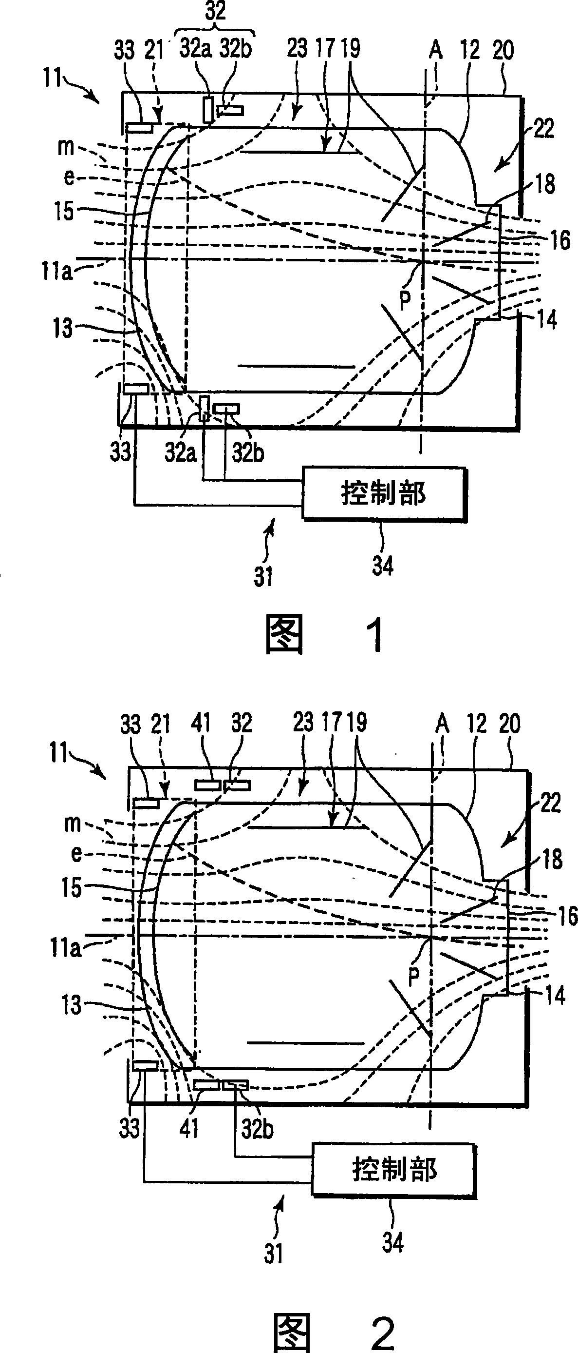
[0021] The first embodiment is shown in Fig. 1 . In FIG. 1 , 11 is an X-ray picture tube. The X-ray picture tube 11 has a vacuum envelope 12 , an input window 13 is formed on the X-ray input side of the vacuum envelope 12 , and an output window 14 is formed on the opposite side to the input window 13 . In the vacuum envelope 12 , an input surface 15 that converts X-rays into electrons for emission is provided inside the input window 13 , and an output surface 16 that converts electron beams into visible light images and outputs them is provided inside the output window 14 .

[0022] In the vacuum envelope 12 , an electron lens 17 for accelerating and focusing electron beams is formed along the advancing path of electrons advancing from the input surface 15 to the output surface 16 . The electron lens 17 is composed of a cathode (not shown) that applies a negative voltage to ...


PUM


Abstract

A magnetic sensor (32) detects an external magnetic field (m) to invade from the outside of an X-ray image tube (11) into an electron lens area (23), and a coil (33) arranged in an input face area (21) of the X-ray image tube (11) generates a magnetic field to cancel the external magnetic field (m) so that the influence of the external magnetic field (m) is eliminated to correct the distortion. The magnetic sensor (32) is arranged in the area, which is surrounded by a magnetic shield (20) of the X-ray image tube (11), and in the outer circumference area on the side of the electronic lens area (23) spaced from the input face area (21) of the X-ray image tube (11). The magnetic sensor (32) is less influenced by the magnetic field, which is generated by the coil (33) arranged on the side of the input face area (21) of the X-ray image tube (11), so that it detects the external magnetic field (m) to invade into the electron lens area (23), highly precisely. As a result, a distortion correcting device (31) of the X-ray image tube (11) can correct the distortion automatically.

Description

technical field [0001] The present invention relates to a distortion correcting device of an X-ray picture tube which removes the influence of an external magnetic field and corrects the distortion of a visible light image. Background technique [0002] Generally, X-ray picture tubes are used in medical X-ray diagnostic devices and industrial non-destructive inspection devices. Features that map visible light images. [0003] In the stage of accelerating and focusing the electrons by using the electron lens, when the external magnetic field enters the area constituting the electronic lens, the trajectory of the electrons is bent due to the Lorentz force of the external magnetic field, and the visible light image is distorted. Therefore, a magnetic shield formed of a high magnetic permeability material is arranged to surround the electron lens area so that an external magnetic field does not enter into the electron lens area. This magnetic shield is not provided between the...

Claims


Application Information

Patent Timeline
Patent Type & Authority Applications(China)
IPC IPC(8): H01J31/50
CPCH01J29/003
Inventor 高桥淳一君岛隆之小高健太郎
Owner KK TOSHIBA
Why Eureka
Try Eureka