Pick-and-place machine comprising a locking device for coupling a feeding unit to it

A technology of interlocking mechanism and conveying device, applied in the direction of electrical components, electrical components, etc., can solve problems such as loss of data, and achieve the effect of improving operational reliability

Active Publication Date: 2008-01-09
ASM ASSEMBLY SYST GMBH & CO
View PDF1 Cites 5 Cited by
  • Summary
  • Abstract
  • Description
  • Claims
  • Application Information

AI Technical Summary

Problems solved by technology

A said plug-in connection, which can be disconnected by the operator at his own discretion, has the disadvantage that due to sudden disconnection of

Method used


Image

  • Pick-and-place machine comprising a locking device for coupling a feeding unit to it
  • Pick-and-place machine comprising a locking device for coupling a feeding unit to it

Examples


Embodiment Construction

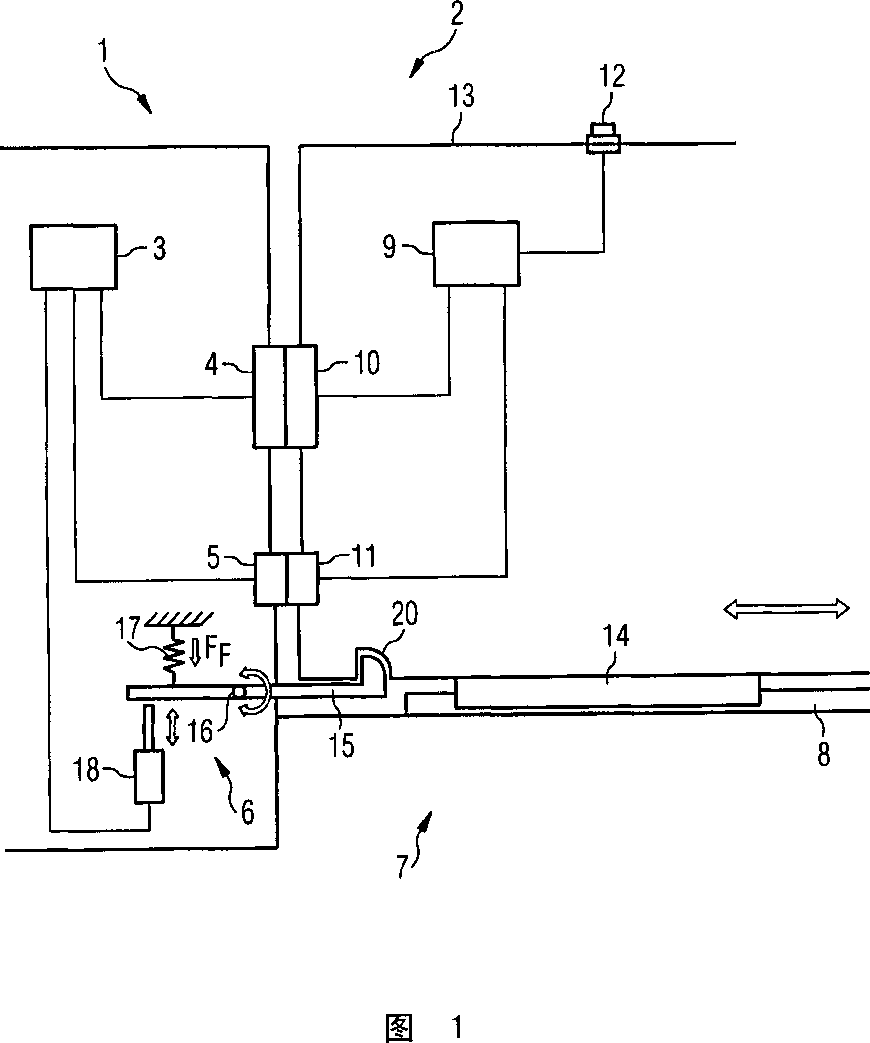
[0025] FIG. 1 shows the main components of an exemplary embodiment of an automatic assembly machine 1 according to the invention, to which a conveyor device 2 according to the invention is coupled. The automatic assembly machine 1 (shown on the left in FIG. 1 ) has a first control device 3 , a first data interface 4 , a first energy interface 5 and a coupling device 2 (shown on the right in FIG. 1 ). out) interlock mechanism 6. Both the first energy connection 5 and the first data connection 4 are electrically connected to the first control device 3 . Furthermore, the first control device 3 is electrically connected to the assembly head and the positioning system of the assembly head (both are not shown). Furthermore, the automatic assembly machine 1 comprises a table 7 for fastening the conveyor devices 2 , on the upper side of which table 7 guide rails 8 for one or more conveyor devices 2 are arranged.

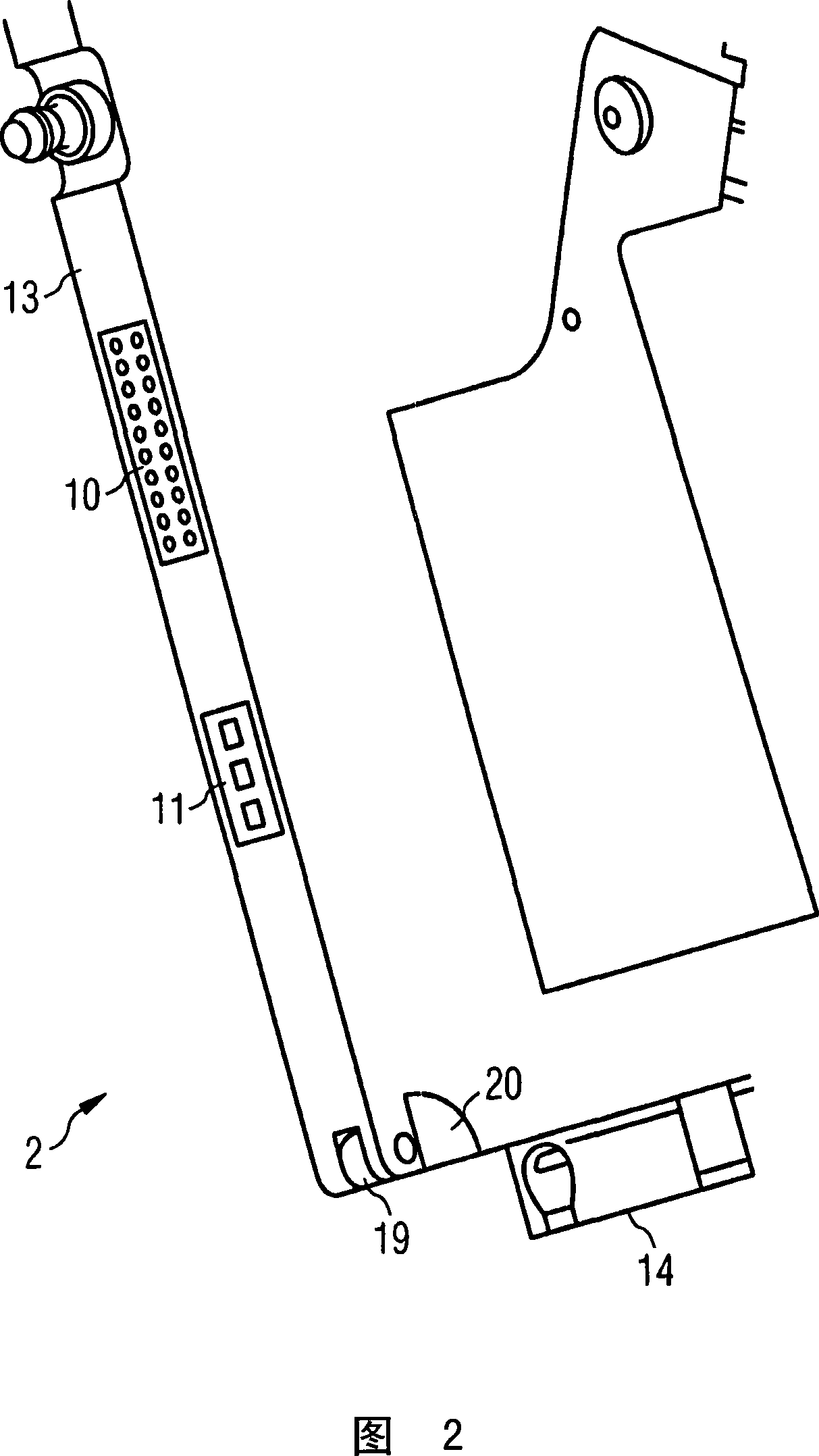
[0026] The delivery device 2 according to the invention itself has a ...


PUM


Abstract

The invention relates to a pick-and-place machine (1) for placing components on substrates. Said machine comprises a detachable locking device (6) for firmly coupling a feeding unit (2) for electrical components to the pick-and-place machine (1), and a first control device (3). Said control device is connected to the locking device (6) in such a manner that the locking device (6) can be optionally locked or unlocked by means of the first control device (3).

Description

technical field [0001] The present invention relates to an automatic mounting machine for assembling substrates with electrical components, a conveying device and a control method for such an automatic mounting machine, wherein the automatic mounting machine has a coupling for coupling the conveying device lock mechanism. Background technique [0002] In an automatic assembly machine, the substrate is assembled with electrical components. The assembly head of the automatic assembly machine, which can be moved over the working area of ​​the automatic assembly machine by means of a positioning system, receives the electronic components in the pick-up area of ​​said automatic assembly machine and transports them to the assembly area, in which The base is assembled. In the pick-up area, the components are supplied by means of one or more conveyor devices which are coupled laterally to the automatic assembly machine in most cases along the assembly line. Most of the conveying ...

Claims


Application Information

Patent Timeline
IPC IPC(8): H05K13/02
CPCH05K13/021
Inventor G·贝耶F·埃申维克T·利贝克D·帕拉斯A·沃兹舍克
Owner ASM ASSEMBLY SYST GMBH & CO
Why Eureka
Try Eureka