
Laser processing device

A laser processing and laser technology, which is applied in laser welding equipment, metal processing equipment, manufacturing tools, etc., can solve the problems of laser irradiation point stability error, laser optical axis swing is not allowed, and achieve the effect of improving the correction accuracy

Inactive Publication Date: 2012-05-23
RAINBOW SUN
View PDF1 Cites 0 Cited by
  • Summary
  • Abstract
  • Description
  • Claims
  • Application Information

AI Technical Summary

Problems solved by technology

[0007] However, when the processing accuracy is below the nanometer unit, the error caused by the position detector of the movable table can tolerate the error of the laser processing device, but the oscillation of the laser optical axis is not allowed, and the stability of the laser irradiation point Errors caused by the

Method used


Image

  • Laser processing device
  • Laser processing device
  • Laser processing device

Examples


Embodiment 1

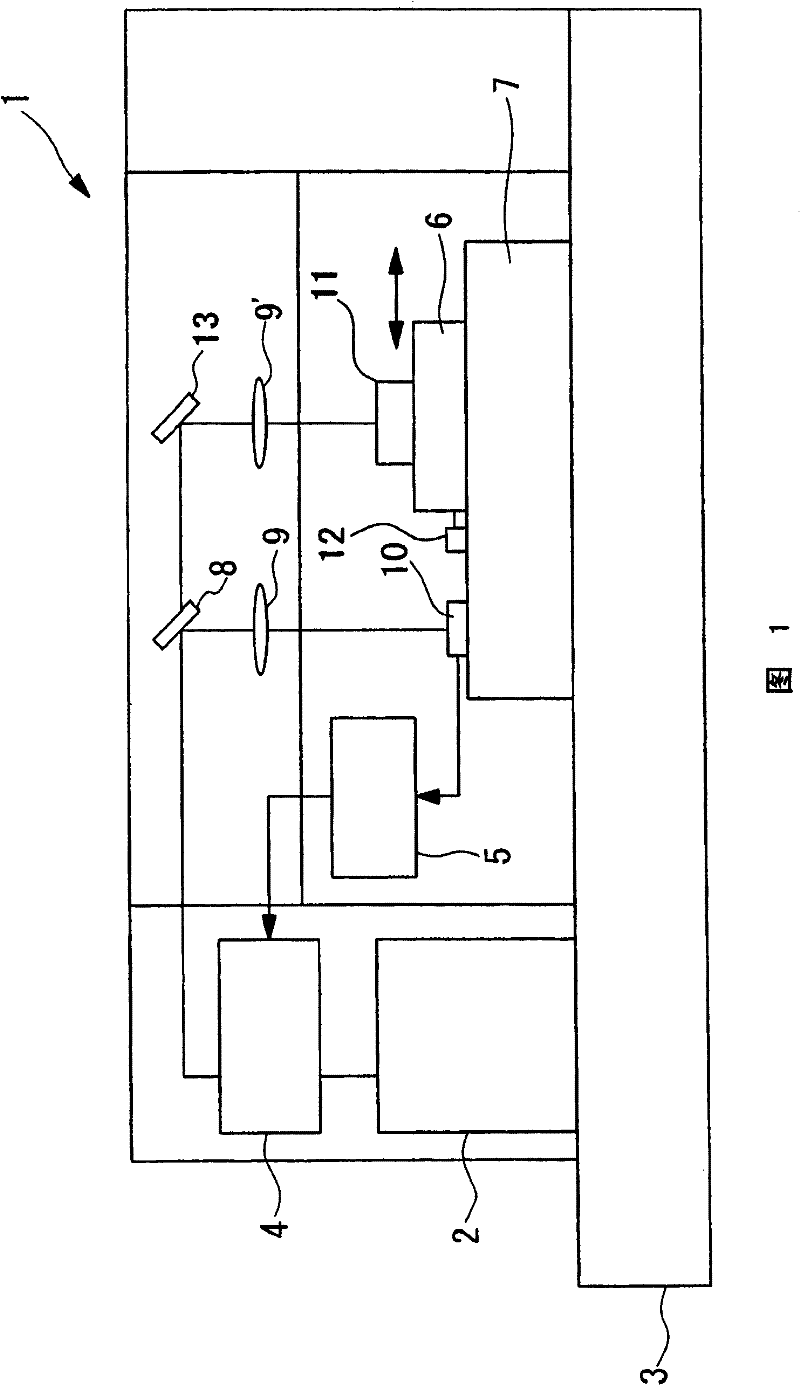
[0044] figure 1 A schematic diagram showing the overall structure of the laser processing apparatus 1 of the present invention with nanometer unit precision. The laser processing apparatus 1 includes: a light source 2, an optical path adjustment unit 4, a half lens (first beam splitter) 8, a total reflection mirror 13, a movable table 6, a movable table position detector 12, and a first optical axis position detector (Photodetector) 10, stage 7, optical axis control unit 5, condenser lenses 9, 9'. In addition, all the components 1 to 12 are arranged on the anti-vibration table 3.


PUM


Abstract

The invention aims at assuring the stability of a laser optical axis. A laser processing device of the invention comprises: a light source, which outputs the laser; a light path adjusting part, which adjusts the light path of the laser; a first light splitter, which splits the light of the laser; a movable station, which is provided with a prescribed movable area and loads the processed objects;a position detector of the movable station, which detects the position of the movable station; a position detector of a first optical axis, which detects the position of the optical axis of the laserthat is obtained by light splitting in the above mentioned; a loading station, which loads the movable station, the position detector of the movable station and the position detector of a first optical axis; an optical axis controlling part, which receives the output data from the position detector of the first optical axis, controls the adjusting part of the light path, and adjusts the optical axis of the laser obtained by light splitting.

Description

Technical field [0001] The invention relates to a laser processing device, in particular to a laser processing device with precision above nanometer level. Background technique [0002] Generally, a laser processing device is equipped with a laser light source that irradiates the workpiece, and a precision table equipped with a movable table on which the workpiece is placed, and has vibration resistance, and has the following steps: Fix the reference of the laser output from the laser light source Point, move the movable table on the XY plane on the precision table to process the workpiece. In this processing process, considering the error of the position detector that detects the position of the movable table on the precision table, and the error of the laser optical axis caused by the light guide path from the laser light source to the workpiece, the movable table The accuracy of the position detector can achieve accuracy below 10nm, and the stability accuracy of the laser opt...

Claims


Application Information

Patent Timeline
Patent Type & Authority Patents(China)
IPC IPC(8): B23K26/04B23K26/067B23K26/042
Inventor 奥野雅史渡部明
Owner RAINBOW SUN
Learn More