Multifunctional detecting device for engine

A detection device and multi-functional technology, which is applied in the field of multi-function detection devices for engines, can solve problems such as complicated wiring, achieve cost-effective, improve thermal conductivity, and increase the degree of freedom

Inactive Publication Date: 2008-01-16
TOYO DENSO
View PDF3 Cites 7 Cited by
  • Summary
  • Abstract
  • Description
  • Claims
  • Application Information

AI Technical Summary

Problems solved by technology

Therefore, since the output lines are also separately wired from each connector to the control ECU, there is a problem that the wiring becomes complicated.

Method used


Image

  • Multifunctional detecting device for engine
  • Multifunctional detecting device for engine
  • Multifunctional detecting device for engine

Examples


Embodiment Construction

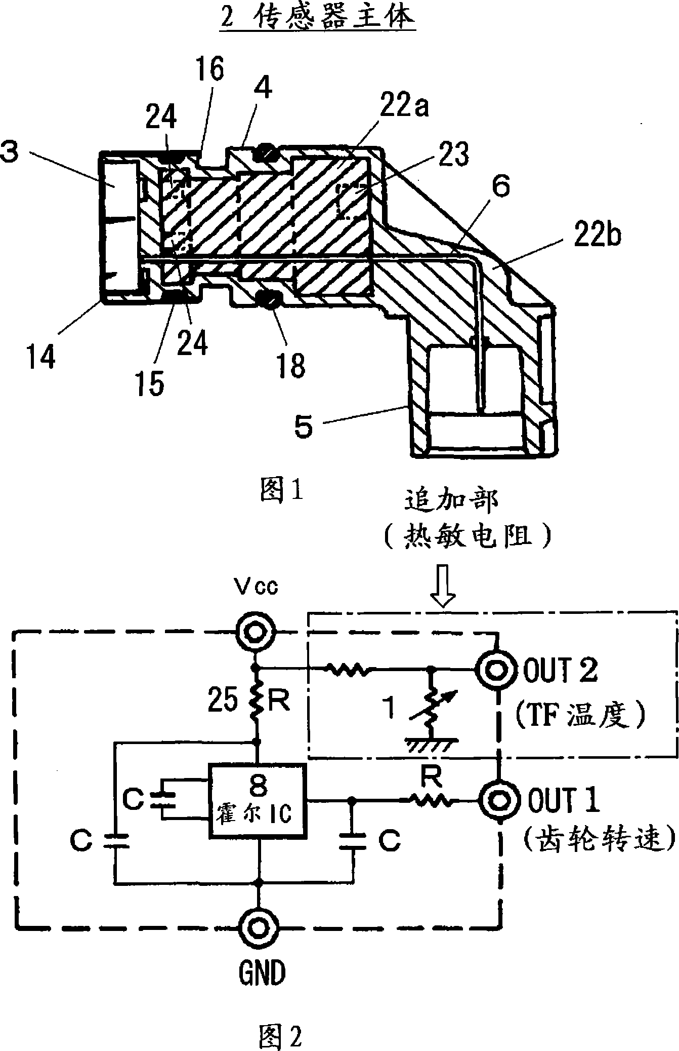
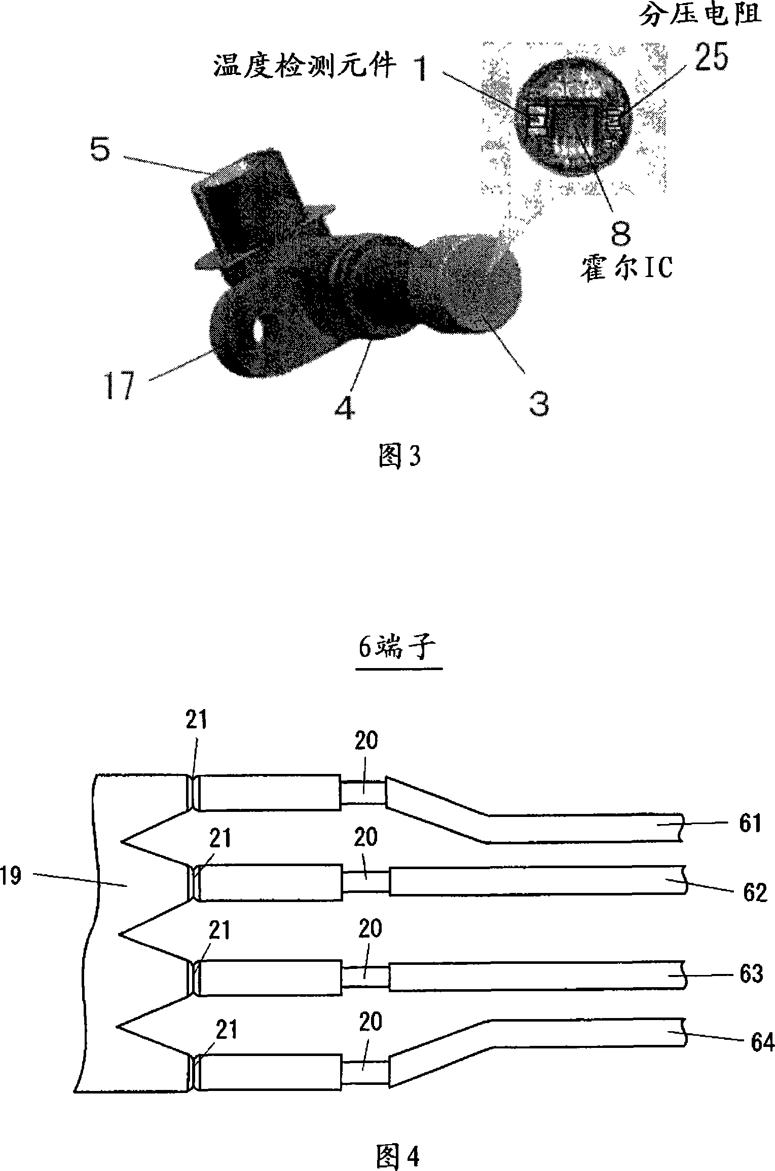
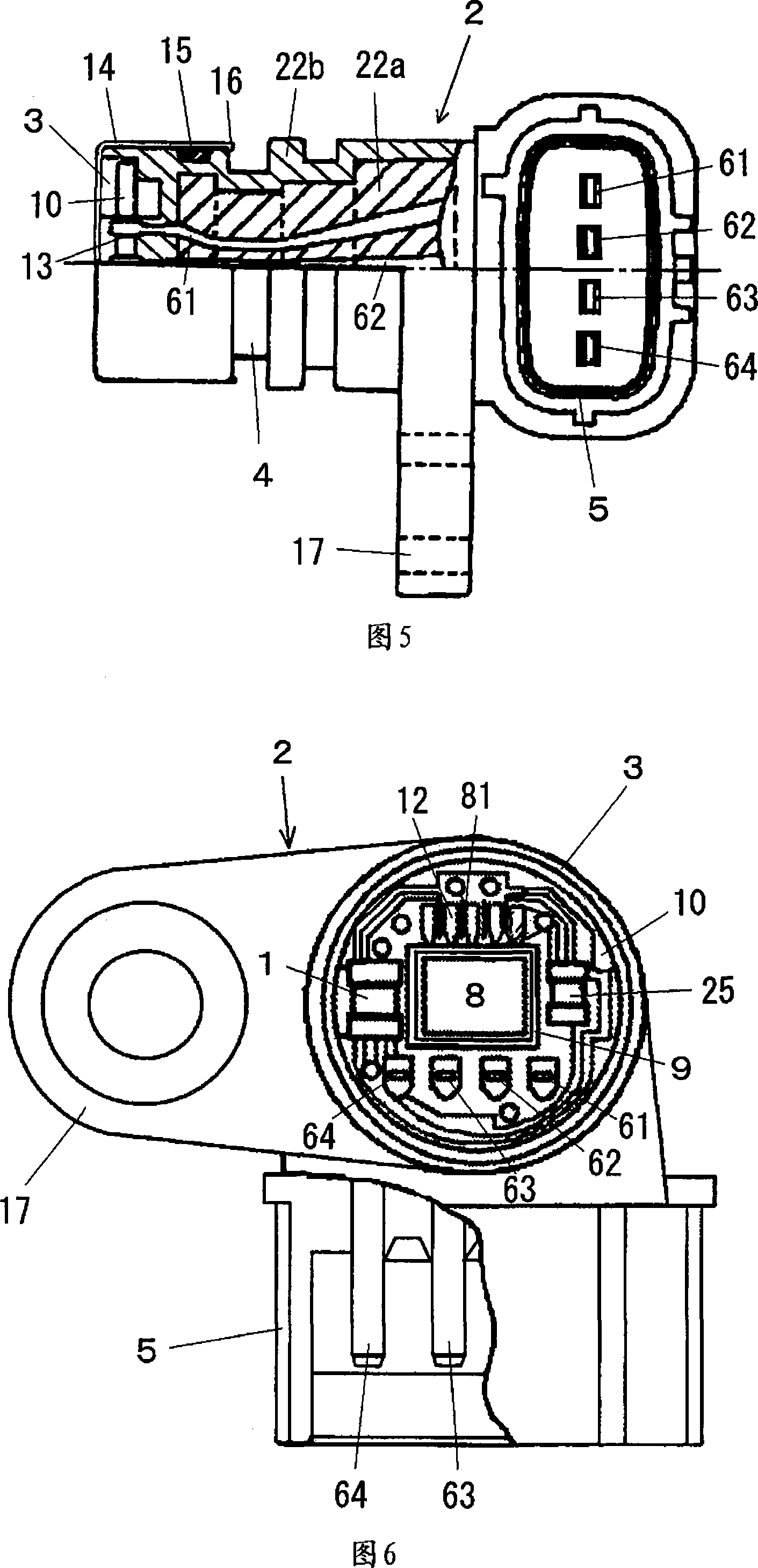
[0028]An embodiment of a multi-function detection device for an engine according to the present invention will be described with reference to FIGS. 1 to 6 . Fig. 1 is a front sectional view of this embodiment, in which, 2 is the sensor main body, 3 is the sensor storage chamber, 4 is the case part, 5 is the connector part, 6 is the external lead terminal, and 22a is the one-time molding Body, 22b is a secondary compression molded body. At one end of the sensor body 2 is disposed a sensor housing portion 3 for housing a sensor circuit board in which two sensors and other components are disposed, and a connector 5 is disposed at the other end of the sensor body 2 . As can be seen from the plan view shown in FIG. 3 , the external shape of the multifunctional detection device for an engine of the present invention is constituted such that the sensor main body 2 of the rotation detector is integrally made of resin via a shell portion 4 having a shape such as overlapping cylinders. ...


PUM


Abstract

The object of the present invention is to provide a multifunctional detector wherein two sensors, for detecting the rotational speed of the transmission gear and for detecting the temperature of the transmission oil are disposed in proximity in a single unit so that they can be connected easily to a control ECU through a single connector. The multifunctional detector for an engine according to the present invention is configured such that a sensor for detecting the rotational speed of the gear within a transmission for a vehicle and a sensor for detecting the temperature of the surrounding transmission oil are mounted on the same circuit board and provided in a single case, and such that a housing chamber therefor is filled with a resin having high thermal conductivity, and the outputs of both sensors are performed from a single connector.

Description

technical field [0001] The present invention relates to a multifunctional detection device for an engine, in particular to a composite device of a sensor for detecting the spindle speed of a transmission of an engine such as an automobile and a sensor for detecting the temperature of transmission oil of a control gear of the transmission. Background technique [0002] Conventionally, a sensor for detecting the spindle speed of a transmission of an engine of an automobile or the like and a sensor for detecting a transmission oil temperature of the transmission gear are attached to the transmission device as separate devices. Although the above-mentioned sensors are located adjacent to each other, they are installed as independent devices, and the output lines are also wired from the connectors to the control ECU. In addition, in addition to this, the transmission device is also equipped with many types of sensors, and the surrounding wiring is relatively complicated. [0003...

Claims


Application Information

Patent Timeline
Patent Type & Authority Applications(China)
IPC IPC(8): G01M15/04
CPCG01K1/14G01P3/44G01P3/487G01K13/08
Inventor 大岛定良菅原亨
Owner TOYO DENSO
Why Eureka
Try Eureka