Backlight module

A technology of backlight components and backplanes, applied in optics, nonlinear optics, instruments, etc., can solve problems such as damage, labor, and time.

Active Publication Date: 2008-01-16
AU OPTRONICS CORP
View PDF0 Cites 6 Cited by
  • Summary
  • Abstract
  • Description
  • Claims
  • Application Information

AI Technical Summary

Problems solved by technology

[0005] However, the above-mentioned steps are labor-intensive and time-consuming. In addition, when the lamp tube 14 passes through the O-ring 15, it is very easy to be damaged due to improper operation.

Method used


Image

  • Backlight module
  • Backlight module
  • Backlight module

Examples


Embodiment Construction

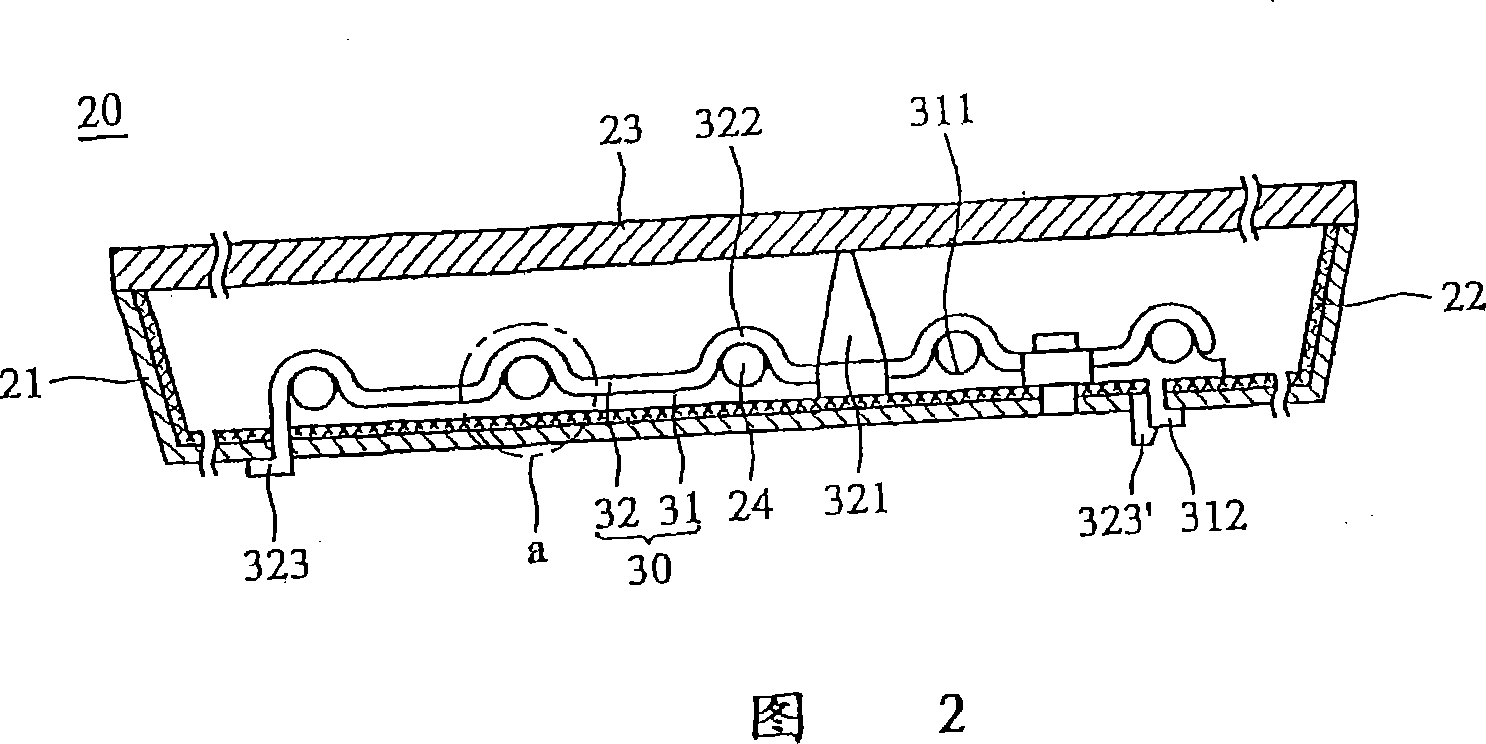
[0041] A direct-lit backlight assembly of a preferred embodiment of the present invention is shown in FIG. 2 . In order to simplify the diagram, FIG. 2 only shows an improved support structure and five lamp tubes, but it is not limited to this in practical application.

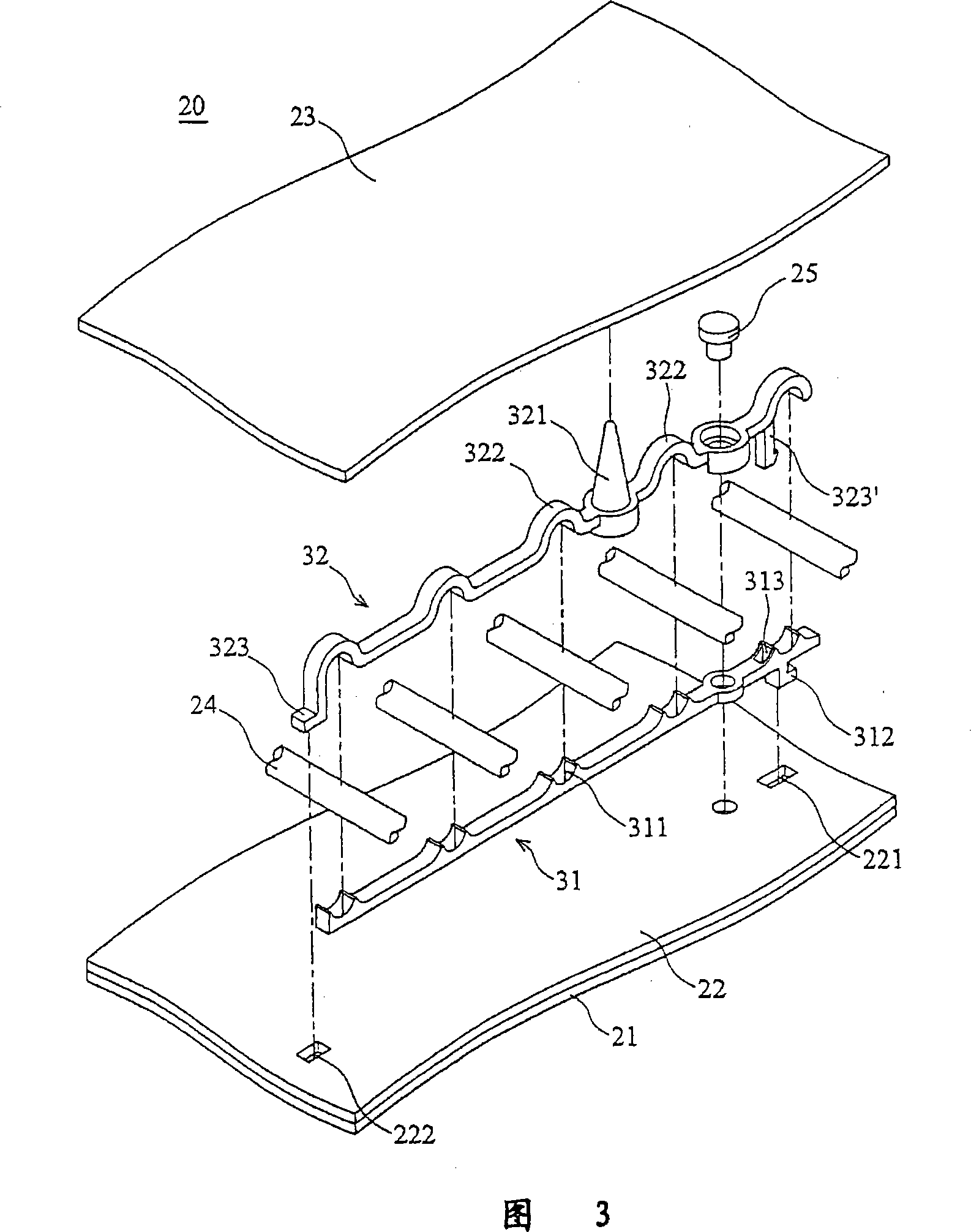
[0042] The direct type backlight assembly 20 of the present invention includes a backplane 21 , a reflection sheet 22 , a diffusion plate 23 , a plurality of lamp tubes 24 and a support member 30 . The surface of the back plate 21 is provided with a plurality of reflective sheets 22 for reflecting light; the diffuser plate 23 is installed on the back plate 21 to form an enclosed space; the support member 30 is arranged between the reflective sheet 22 and the diffuser plate 23, including a The base 31 and a fixing part 32 are clamped by the base 31 and the fixing part 32 , and are arranged at intervals between the reflection sheet 22 and the diffuser plate 23 , serving as light sources of the backlight assembly....


PUM


Abstract

A backlight component comprises a back plate, a diffusion plate, a supporting piece and a plurality of lighting tubes; wherein the diffusion plate is equipped on the back plate; the supporting piece is equipped between the back plate and the diffusion plate; furthermore, the supporting piece comprises a base and a fixing piece; the fixing piece has a supporting part connected against the diffusion plate, which can prevents the diffusion plate from bending and deforming; a plurality of lighting tubes are equipped between the base and the fixing piece and are taken as the light source of the backlight component.

Description

[0001] This application is a divisional application of the invention patent application with the application number 200510005833.8 entitled "Backlight Assembly" submitted to the China Patent Office by AU Optronics Co., Ltd. on January 27, 2005. technical field [0002] The present invention relates to a backlight assembly, in particular to a backlight assembly with a spacer to maintain a predetermined distance between a diffuser plate and a light source. Background technique [0003] Generally, a liquid crystal display uses a backlight assembly as a light source, and the backlight assembly can be divided into two types: side-light type and direct-light type, depending on the location of the light source. As shown in FIG. 1 , the direct-lit backlight assembly 10 includes a reflector 11 , a diffusion plate 12 , a plurality of support columns 13 and a plurality of lamp tubes 14 . The reflector 11 is located at the bottom of the backlight assembly 10, the diffusion plate 12 is a...

Claims


Application Information

Patent Timeline
Patent Type & Authority Applications(China)
IPC IPC(8): G02F1/13357G02F1/1333G02F1/1335
Inventor 赖清坤李重德
Owner AU OPTRONICS CORP
Why Eureka
Try Eureka