Magnetic canister drive speed-adjusting clutch

A clutch and speed regulation technology, applied in the field of clutches, can solve the problems of high cost, high heat generation, small transmission torque, etc., and achieve the effects of low manufacturing, use and maintenance costs, small power loss, and large transmission torque

Inactive Publication Date: 2008-01-16
巩长勇
View PDF0 Cites 6 Cited by
  • Summary
  • Abstract
  • Description
  • Claims
  • Application Information

AI Technical Summary

Problems solved by technology

[0002] At present, there are two methods of speed-regulating clutches, one is to transmit torque through the shear force of the liquid, and adjust the speed by adjusting the distance between the active friction plate and the passive friction plate of the transmission mechanism, thereby changing the thickness of the sheared liquid film , the clutch has low transmission efficiency, high heat generation, complex structure, difficult manufacturing, high cost and high failure rate
The other is to install two rings opposite to each other on the driving shaft and the driven shaft, one of which is magnetic. When the two rings move relative to each other, the rotation of the magnetic ring makes the corresponding ring cut the magnetic force line and generate induction. The current generates an induced magnetic field, and the torque and rotation are transmitted through the interaction of the induced magnetic field and the magnetic field of the magnetic ring, and the magnetic force is changed by changing the distance between the two ends for speed regulation. The clutch only has two ends for magnetic transmission. The transmission torque is small and the volume is large, which cannot meet the requirements of high torque transmission
[0003] This shows that above-mentioned existing speed-regulating clutch obviously still has inconvenience and defect in structure and use, and urgently needs to be further improved

Method used


Image

  • Magnetic canister drive speed-adjusting clutch
  • Magnetic canister drive speed-adjusting clutch
  • Magnetic canister drive speed-adjusting clutch

Examples


Embodiment 1

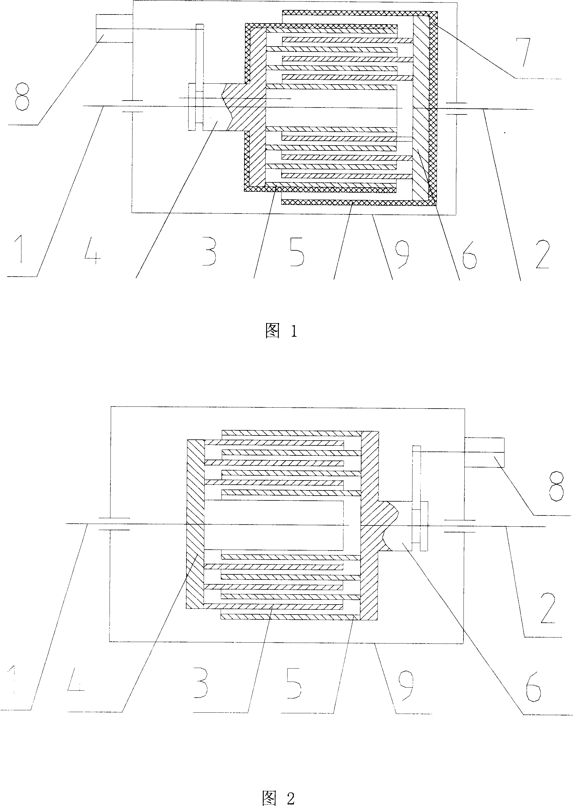
[0025] Please refer to shown in Fig. 1, the magnetic cylinder transmission speed regulating clutch of preferred embodiment of the present invention, comprises transmission shaft I (1), transmission shaft II (2), one or more than one transmission member I (3), fixed body I (4), one or more transmission parts II (5), fixed body II (6), magnetic isolation sleeve (7), adjustment mechanism (8), body (9), in which: transmission shaft I (1) The transmission shaft II (2) and the adjustment mechanism (8) are respectively installed on the body (9), the fixed body I (4) is installed on the transmission shaft I (1), and the fixed body II (6) is installed on the transmission shaft II ( 2), the transmission part I (3) and the transmission part II (5) are both cylindrical, and their diameters are different from each other. Any two pieces can be set together. The transmission part I (3) and the transmission part II (5) )--interlaced at intervals and coaxially installed on the fixed body I (4)...

Embodiment 2

[0029] Please refer to shown in Fig. 2, the magnetic cylinder transmission speed regulating clutch of preferred embodiment of the present invention, comprises transmission shaft I (1), transmission shaft II (2), one or more than one transmission member I (3), fixed body I (4), one or more transmission parts II (5), fixed body II (6), adjustment mechanism (8), body (9), wherein: transmission shaft I (1) and transmission shaft II (2) They are coaxially installed on the machine body (9), the fixed body I (4) is installed on the transmission shaft I (1), the fixed body II (6) is installed on the transmission shaft II (2), and the transmission part I ( 3) is a cylinder, the other transmission parts I (3) and all transmission parts II (5) are cylinders, all transmission parts I (3) and transmission parts II (5) have different diameters, and any two parts can Sleeved together, the transmission part I (3) and the transmission part II (5) are interlaced with each other at intervals and...

Embodiment 3

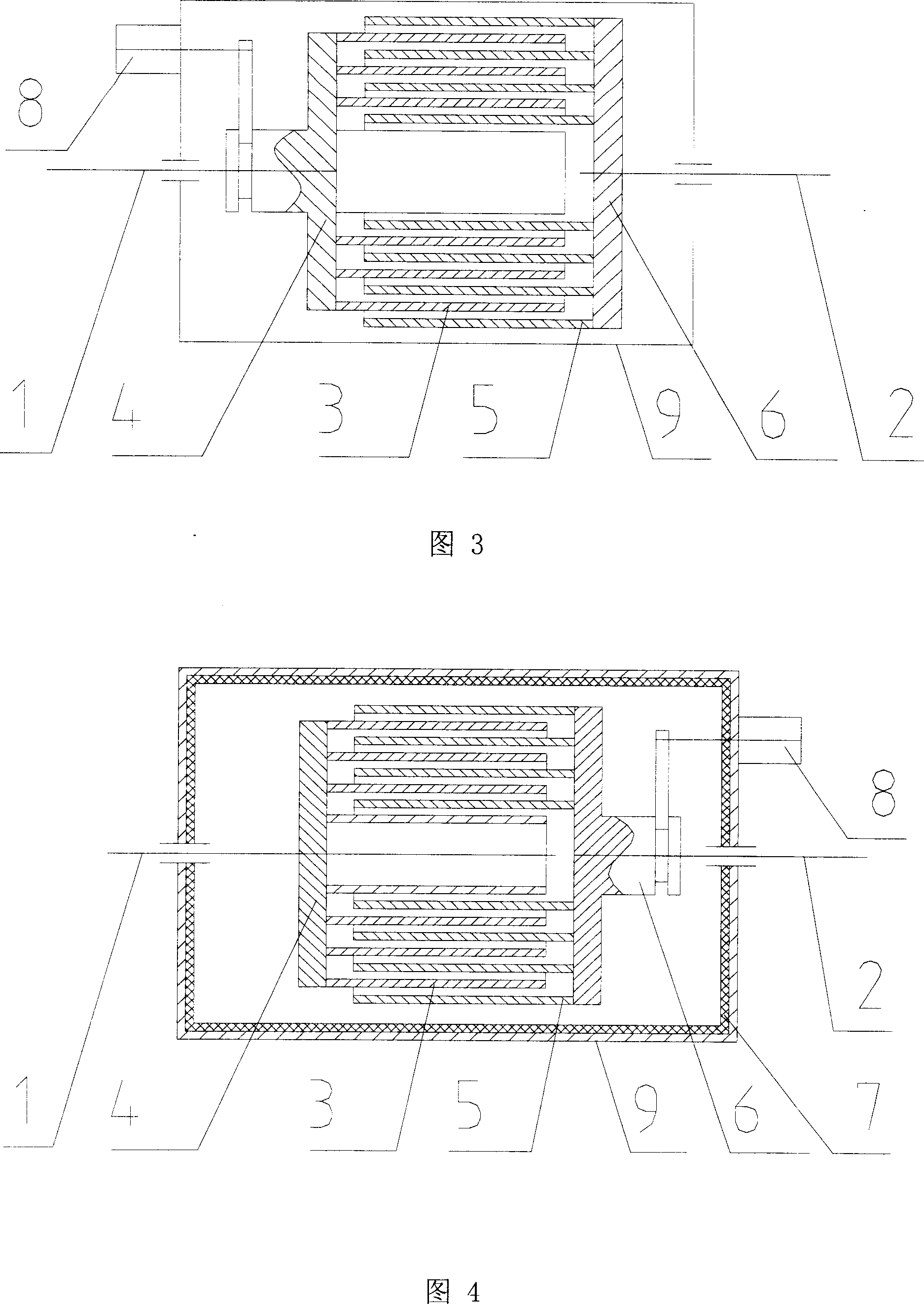
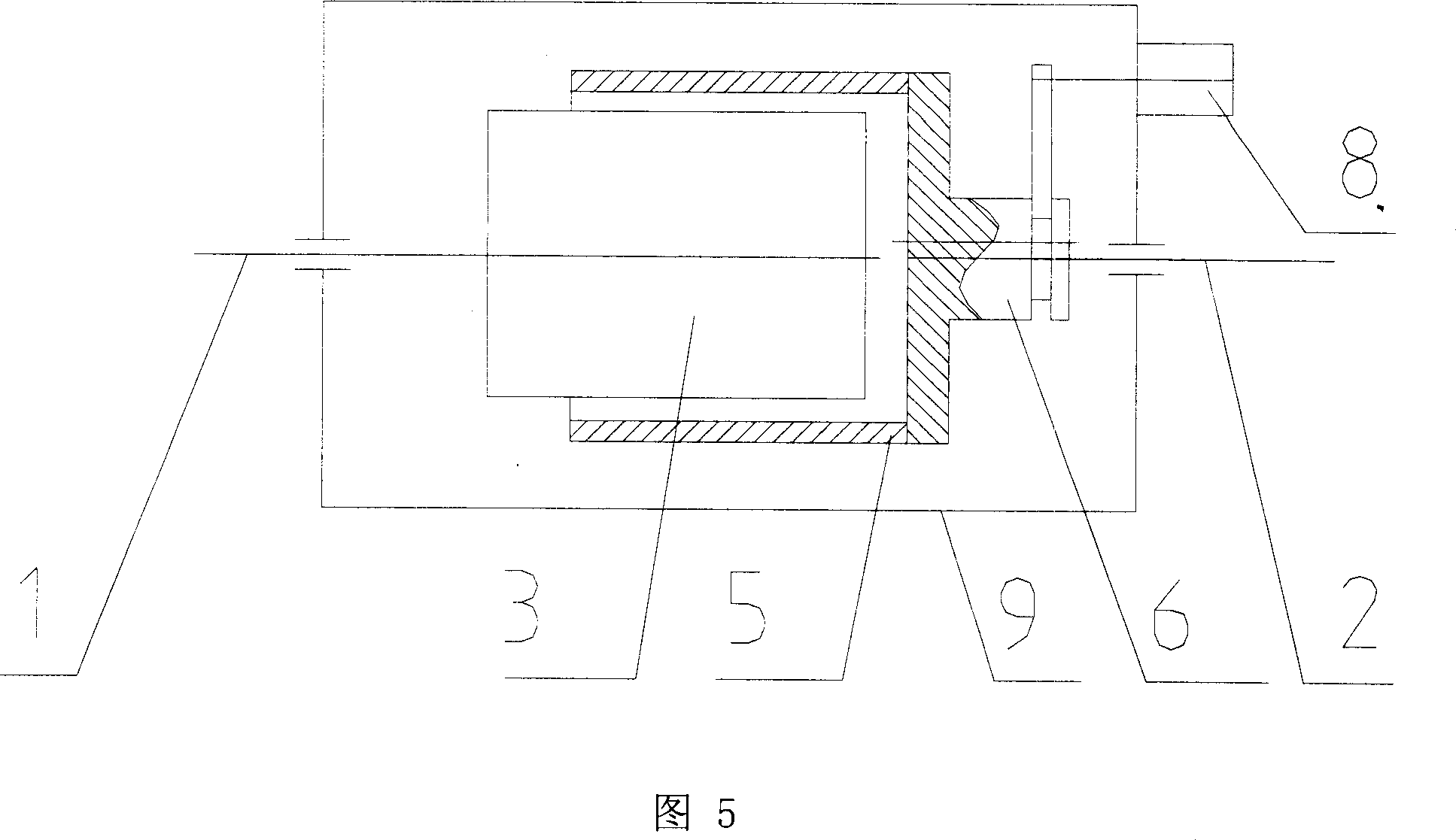
[0031]Please refer to shown in Fig. 3, the magnetic cylinder transmission speed regulating clutch of preferred embodiment of the present invention, comprises transmission shaft I (1), transmission shaft II (2), one or more than one transmission member I (3), fixed body I (4), one or more transmission parts II (5), fixed body II (6), adjustment mechanism (8), body (9), wherein: transmission shaft I (1) and transmission shaft II (2) The coaxial shafts are respectively installed on the body (9), the fixed body I (4) is installed on the transmission shaft I (1), the fixed body II (6) is installed on the transmission shaft II (2), except for the transmission part I with the smallest diameter (3) is a cylinder, and the rest of the transmission part I (3) and the transmission part II (5) are cylindrical, and their diameters are different from each other. Any two pieces can be set together. The transmission part I (3) and the transmission part Pieces II (5) are interlaced with each ot...


PUM


Abstract

The invention discloses a transmission speed regulation clutch of magnetic cylinder, to provide a speed regulation clutch with low abrasion, high carrying capability and overload protection. The invention comprises a transmission axis I, a transmission axis II, transmission members I, a fixture I, transmission members II, a fixture II, a regulation mechanism and a main body. The fixture I and the fixture II are respectively arranged on the transmission axis I and the transmission axis II. The transmission members I and the transmission members II are coaxially arranged on the fixture I and the fixture II respectively. The transmission axis I, the transmission II and the regulation mechanism are arranged on the main body. The fixture I or the fixture II are connected with the regulation mechanism. The regulation mechanism is able to drive the transmission members I or the transmission members II to axially move, to make the transmission members I and the transmission members II capable of being inserted into and extracted out each other. All transmission members I and the transmission members II are magnetic, or the partial magnetic transmission members I and the transmission members II are electromagnetic induction parts. The invention is suitable for soft start, startup and brake, overload protection.

Description

technical field [0001] The invention relates to a clutch, in particular to a magnetic cylinder drive speed regulating clutch capable of transmitting torque through magnetic force and capable of speed regulation. Background technique [0002] At present, there are two methods of speed-regulating clutches, one is to transmit torque through the shear force of the liquid, and adjust the speed by adjusting the distance between the active friction plate and the passive friction plate of the transmission mechanism, thereby changing the thickness of the sheared liquid film , the clutch has low transmission efficiency, high heat generation, complex structure, great manufacturing difficulty, high manufacturing cost and high failure rate. The other is to install two rings opposite to each other on the driving shaft and the driven shaft, one of which is magnetic. When the two rings move relative to each other, the rotation of the magnetic ring makes the corresponding ring cut the magnet...

Claims


Application Information

Patent Timeline
Patent Type & Authority Applications(China)
IPC IPC(8): H02K49/00H02K49/10H02K51/00
Inventor 巩高铄
Owner 巩长勇
Why Eureka
Try Eureka