Rotation lifting mechanism in steel tube quenching device and steel tube quenching method

A technology of rotating lifting and quenching devices, applied in the direction of quenching devices, furnaces, heat treatment equipment, etc., can solve problems such as the need to improve safety and reliability, not suitable for quenching process and overall equipment requirements, and defects in the automatic lifting and accurate positioning of steel pipes, etc., to achieve Superior technical effects and comprehensive functions, compaction and discharge technical effects and comprehensive functions

Inactive Publication Date: 2010-06-09
CHINA NAT HEAVY MACHINERY RES INSTCO
View PDF7 Cites 2 Cited by
  • Summary
  • Abstract
  • Description
  • Claims
  • Application Information

AI Technical Summary

Problems solved by technology

Among the currently disclosed technical devices, there are functional deficiencies to varying degrees. For example, the patented technology No. 97218368. The safety and reliability in the rotating state still needs to be improved; another example is the patented technology No. 200520043055.7, although it can achieve three-dimensional adjustment of the relative position of the quenching parts, it is obviously not suitable for the overall requirements of the quenching process and equipment in the steel pipe tank

Method used


Image

  • Rotation lifting mechanism in steel tube quenching device and steel tube quenching method
  • Rotation lifting mechanism in steel tube quenching device and steel tube quenching method
  • Rotation lifting mechanism in steel tube quenching device and steel tube quenching method

Examples


Embodiment Construction

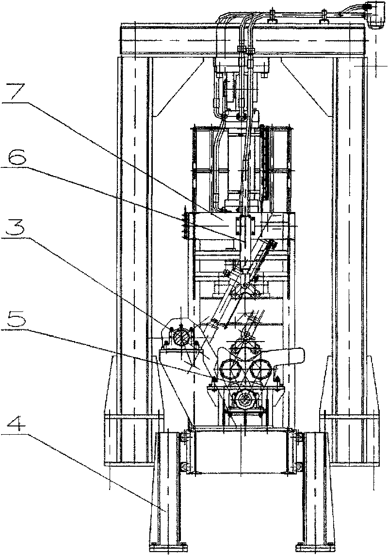
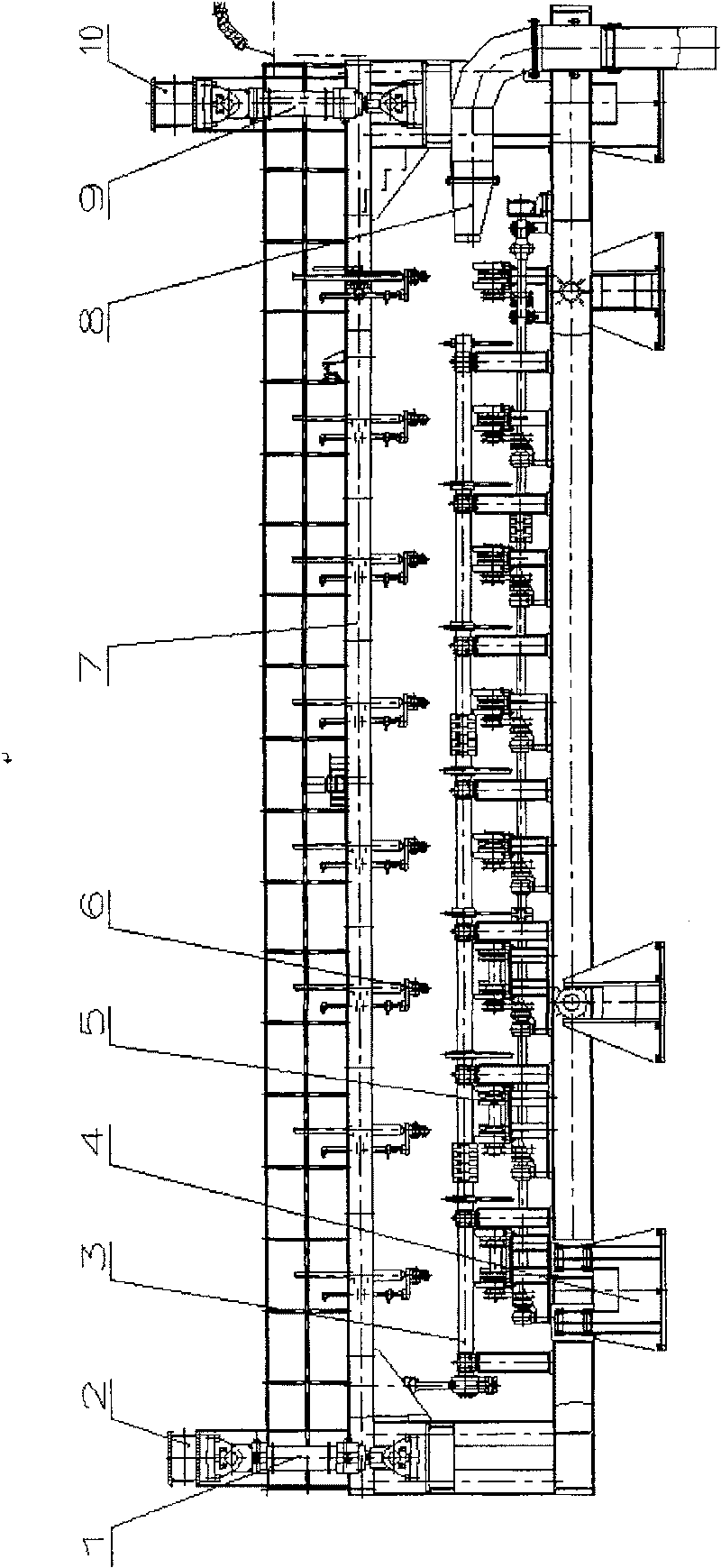
[0016] The equipment structure of the present invention adopts double oil cylinders as power to drive the frame beam to move up and down, from this embodiment figure 1 with figure 2 It can be seen that the rotary lifting mechanism at least includes a left lifting cylinder 1, a left supporting beam 2, a right lifting cylinder 9, a right supporting beam 10, a frame beam 7, a blanking flap 3, a guide bracket 4, a rotating support 5, and a pressing device 6. Internal spray nozzle 8. The anchor bolts at the bottom of the left support beam 2 and the right support beam 10 are fixed to the foundation; the upper part of the left lift cylinder 1 is hinged with the left support beam 2, and the lower part is hinged with the frame beam 7; the upper part of the right lift cylinder 9 is hinged with the right support beam 2, and the lower part It is hinged with the frame beam 7; the left side of the frame beam 7 is hinged with the left lifting cylinder 1, and the right side is hinged with t...


PUM


Abstract

The invention relates to a rotation lifting mechanism of a steel pipe quenching unit and a steel pipe quenching method. The steel pipe quenching method is that when the heated steel pipe is placed ona rotation supporting wheel, the rotation supporting wheel rotates at a speed lower than 10 rotations per minute to 15 rotations per minute; a compaction device distributed along the steel pipe direction closely presses the steel pipe; the rotation supporting wheel drives the steel pipe to rotate at a speed faster than 45 rotations per minute to 120 rotations per minute, and drives a frame beam 7to move downwards at a speed of 150 mm per second to 400 mm per second driven by a left lift cylinder 1 and a right lift cylinder 9 at the same time; the steel pipe is dipped into quenching medium ofa quenching tank, at this time, the inner spraying liquid flushes liquid to the internal of the steel pipe by an inner spraying nozzle always aiming to mouth of the steel pipe and the steel pipe innerwall quenching is carried out; until the temperature of the steel pipe is lower than 300 DEG C., the frame beam 7 is driven by both the left lift cylinder 1 and the right lift cylinder 9 and is lifted, at the same time, the compaction device is opened and a feeding overturn board 3 is turned to the material outlet location from a material receiping location to convey the steel pipe to an inclinedbench.

Description

technical field [0001] The invention relates to metal heat treatment equipment and a design method thereof, in particular to a rotating lifting mechanism applied to a steel pipe quenching device and a steel pipe quenching method. Background technique [0002] With the increasing output of steel pipes and the higher and higher performance of steel pipes, the technical requirements for quenching devices in steel pipe manufacturing are becoming more and more stringent. When the quenching process of "immersion quenching + rotation + internal spraying" is adopted, the rotary lifting mechanism is the core component of the quenching device in the steel pipe tank. In order to meet the straightness of the steel pipe after quenching and the consistency of mechanical properties throughout the length of the steel pipe, it is necessary to design a mechanism that can not only quickly immerse the steel pipe in the quenching medium, but also ensure the high-speed rotation of the steel pipe ...

Claims


Application Information

Patent Timeline
Patent Type & Authority Patents(China)
IPC IPC(8): C21D9/08C21D1/62C21D11/00
Inventor 杜学斌徐能惠雷刚邵国栋任明杰卫凌云
Owner CHINA NAT HEAVY MACHINERY RES INSTCO
Why Eureka
Try Eureka