Polyphase brushless electric motor

A brushless motor and armature technology, applied in the direction of electrical components, electromechanical devices, electric components, etc., can solve problems such as the influence of magnetic flux concentration, and achieve the effect of ensuring magnetic flux concentration, high torque, and multiple parallel air gaps

Inactive Publication Date: 2008-01-23
UNION PLASTIC HANGZHOU MACHINERY +1
View PDF7 Cites 3 Cited by
  • Summary
  • Abstract
  • Description
  • Claims
  • Application Information

AI Technical Summary

Problems solved by technology

Among them, the bar 8 of ferromagnetic material can be used as the magnetic flux return path of the adjacent magnets arranged along the moving direction, but the adjacent magnetic poles will cause the magnetic flux concentration to be affected

Method used


Image

  • Polyphase brushless electric motor
  • Polyphase brushless electric motor
  • Polyphase brushless electric motor

Examples


Embodiment Construction

[0079] The brushless motor of the present invention has an armature member containing several magnetically isolated electromagnet components to interact with a field magnet member containing several magnetic components, so as to obtain concentration of magnetic flux and even utilization of force, and by increasing The pole surface area of ​​the field magnet members and corresponding armature members across several air gaps facilitates a more even utilization of forces, eg Maslov et al. US Patent Grant No. 6891306 and related applications mentioned above.

[0080] The present invention is described in detail below in conjunction with accompanying drawing:

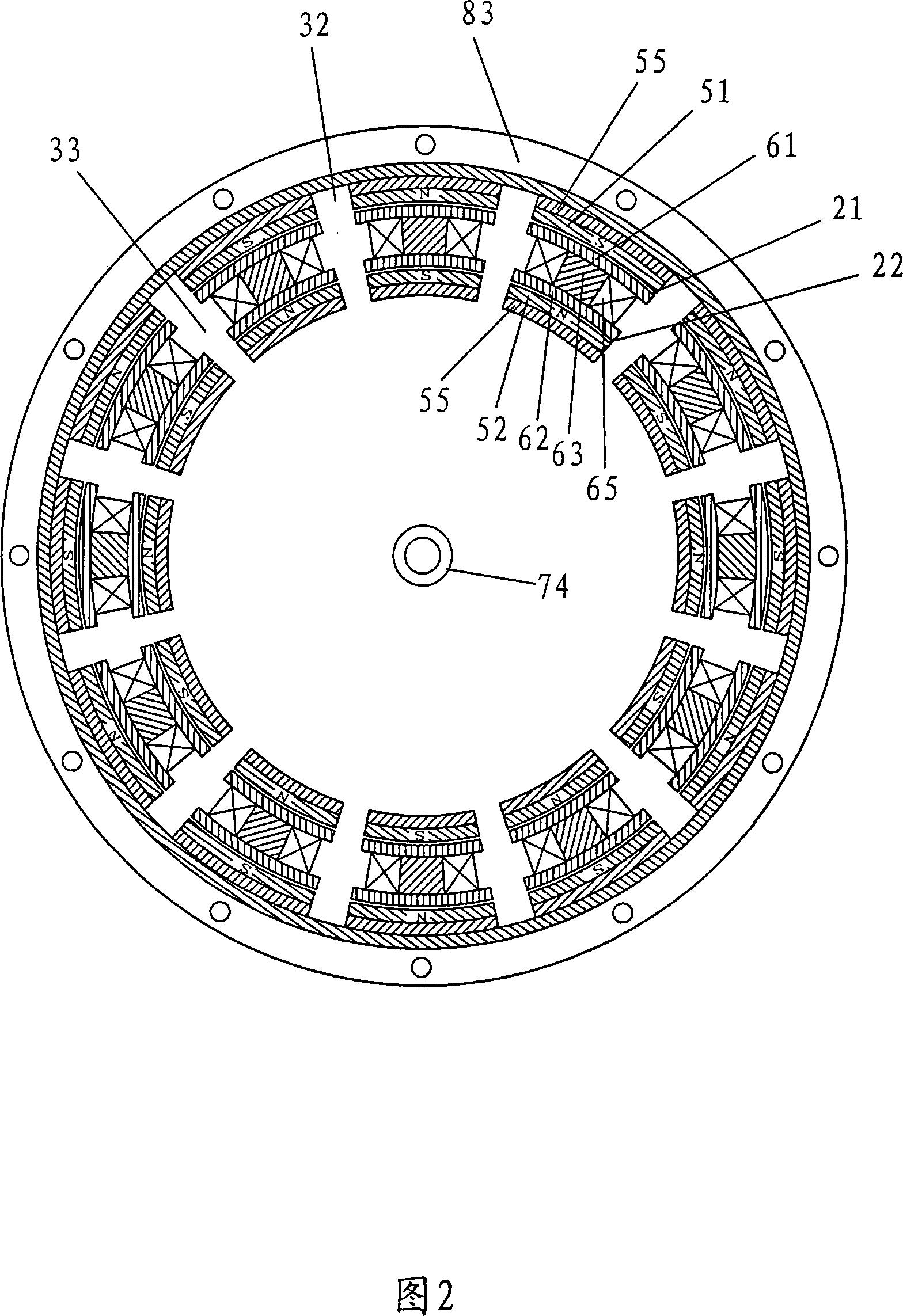
[0081] Fig. 2 is an exemplary cross-sectional view of the field magnet member as the rotor and the armature member as the stator of the brushless motor in Chinese Patent Application No. 200610100123. In the rotor outer ring 83, the rotor contains several magnetic assemblies containing permanent magnets 51 or 52 arranged alon...


PUM


Abstract

A multiphase brushless motor utilizes a multiphase arrangement of armature members in a brushless motor to correlate magnet polar fronts of magnet members with corresponding magnet polar fronts of armature members to achieve mutual deflection and reduce adverse impact of a breakdown torque on an output torque. In addition, with the help of one or more brushless motors, more parallel air gaps are increased in a multiphase brushless motor in a three-dimensional space, thus providing a higher torque output through a multiphase cluster under a condition of limited moving direction. Or more individuals connected in series and moving independently are arranged.

Description

technical field [0001] The invention relates to a motor structure, in particular to a multi-phase brushless motor. Background technique [0002] As far as general rotating electrical machines are concerned, regardless of the operation of DC motors or AC motors, the magnetic principle of like-sex repulsion and opposite-sex attraction is adopted between the rotor and the stator. For linear motors that produce a linear force, the stator and rotor of a rotary motor are replaced with those of a linear motor, but the principle of operation is the same. [0003] Kawai et al. proposed a power generating device in US Patent Grant No. 5,436,518, in which each magnetic circuit of several electromagnets of the stator is arranged to be independent of each other. Because the electromagnets are arranged to have their respective magnetic circuits independent of each other, they are magnetized independently of other electromagnets, and the electromagnets are sequentially excited to control ...

Claims


Application Information

Patent Timeline
Patent Type & Authority Applications(China)
IPC IPC(8): H02K41/00H02K41/02H02K41/03
CPCH02K16/00H02K21/12H02K1/148
Inventor 陆纬庭
Owner UNION PLASTIC HANGZHOU MACHINERY
Why Eureka
Try Eureka