Pneumatic tire

A technology of pneumatic tires and tires, which is applied in the direction of heavy tires, tire parts, tire treads/tread patterns, etc., can solve the problems of reducing the rigidity of the grounding part, increasing the volume of the tread rubber, and poor surface, etc., to achieve the suppression of grounding Partial deformation, ensure the effect of heat dissipation and drainage

Active Publication Date: 2010-05-19
BRIDGESTONE CORP
View PDF7 Cites 0 Cited by
  • Summary
  • Abstract
  • Description
  • Claims
  • Application Information

AI Technical Summary

Problems solved by technology

[0005] However, as in the above-mentioned conventional example, if the tread thickness is increased, the rigidity of the land portion defined by the lug grooves will be reduced, and the part (kick-off end) of the land portion that contacts the road surface last wears more than the first part of the land portion. Tendency to wear (heel and toe wear) on the part in contact with the road surface (step-in end)
[0006] Such an uneven wear pattern will not only make the surface look bad, but also increase the volume of the worn rubber and reduce the wear resistance
[0007] Conventionally, such problems have been dealt with by making the lug grooves of the most worn part shallower to increase the rigidity of the land area. However, in this case, although the deformation of the land area can be suppressed, it also increases the The force that is borne on the ground contact portion cannot achieve a very good effect. In addition, due to the increase in the volume of the tread rubber, there is concern that the temperature of the tire during driving will increase and the durability will deteriorate.

Method used


Image

  • Pneumatic tire
  • Pneumatic tire
  • Pneumatic tire

Examples


no. 1 Embodiment approach

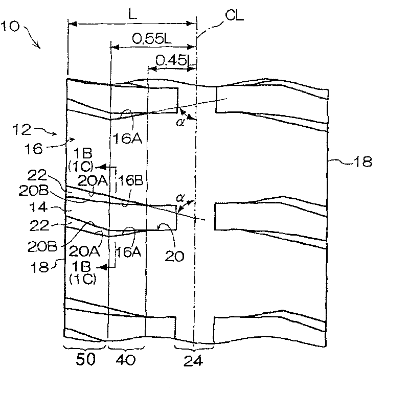
[0058] exist Figure 1A Among them, the pneumatic tire 10 of the present embodiment has, on the tread 12, lug grooves 14 arranged in a direction intersecting with the tire circumferential direction and land portions 16 defined by the lug grooves 14. The center ribs 24 are arranged in the tire circumferential direction and are connected to the land portion 16 on the tire equatorial plane CL. The lug groove 14 terminates on the tire equatorial plane CL side without penetrating the center rib 24 and is formed on the tire axially outer side at least to the ground contact end 18 . Here, small grooves connecting the lug grooves 14 across the tire equatorial plane CL may be arranged in the center rib 24 .

[0059] On the pneumatic tire 10, when the distance from the ground contact end 18 to the tire equatorial plane CL is L when the pneumatic tire 10 is installed on a normal rim to fill it with normal internal pressure and make it bear the normal load, In the area 40 where the dista...

no. 2 Embodiment approach

[0091] In the pneumatic tire 30 of the present embodiment, in the pneumatic tire 10 of the first embodiment, the tread 12 is formed in a region of 0.55L to 0.70L away from the tire equatorial plane CL toward the outside in the tire axial direction. Circumferential grooves 32 extending in the tire circumferential direction.

[0092] Here, the reason why the position where the circumferential direction groove 32 is formed is set in this way is because: if it is less than 0.55L, the rigidity in the vicinity of the circumferential direction groove 32 decreases, thereby reducing the wear resistance; if it is greater than 0.70L, the circumferential direction The effect of the groove 32 is hardly transmitted to the 1 / 4 point, so the influence of the angle of the lug groove near the ground contact end 18 on the effect of suppressing uneven wear cannot be ruled out.

[0093] In addition, considering the influence on cracks at the bottom of the groove, it is preferable that the groove w...

Embodiment 1

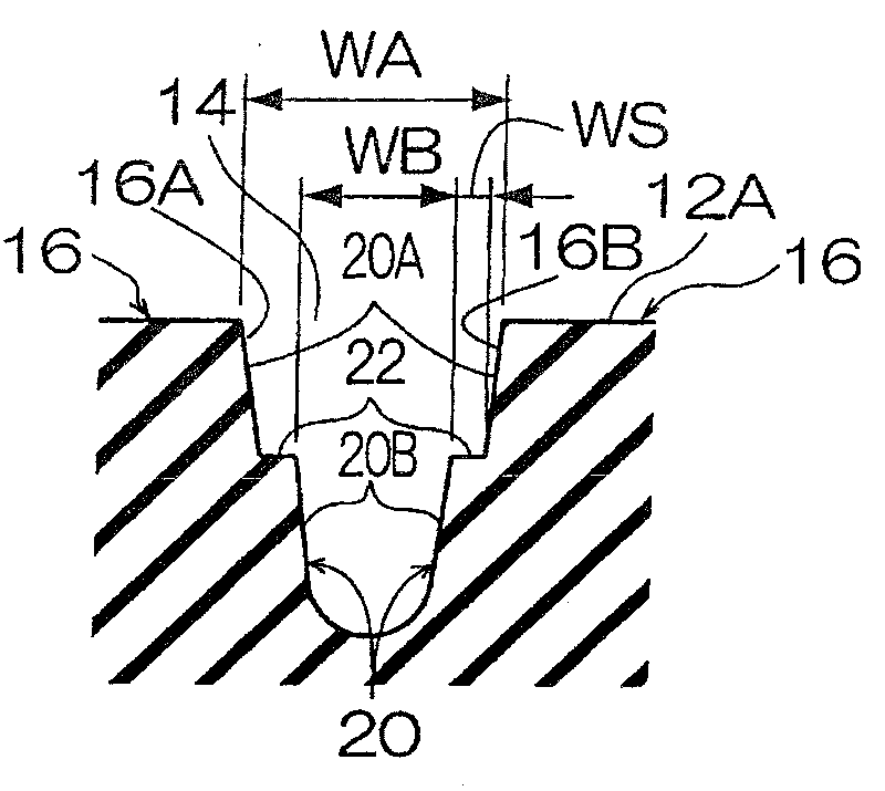
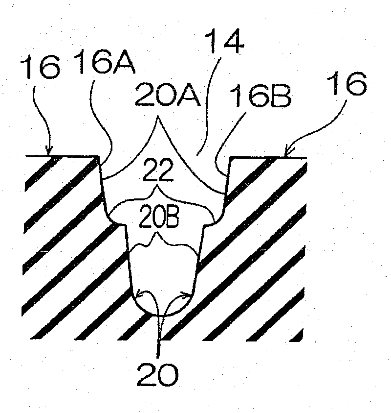
[0103] The pneumatic tire of Example 1 has such Figure 1A , Figure 1B In the shown tread 12 , the inclination angle α of the side groove wall 20A of the tread contact surface is 70° to 85°, and the groove depth of the lug groove 14 is 90 mm. The width WS of the step portion 22 at the ground contact end 18 is 15 mm, and the width gradually decreases toward the tire equatorial plane CL. In addition, the groove width of the lug groove 14 in the vicinity of the tread contact surface 12A of the ground contact end 18 is 80 mm.


PUM


Abstract

A pneumatic tire for heavy duty enabling an increase in the biased abrasion resistance of a tread while maintaining durability. A component (Fin) in the axial inner direction of the tire which is opposite to the axial outer direction of the tire is added to a force acting on the kicking end (16B) of a land portion (16) to suppress wear at the kicking end of the land portion so as to increase the biased abrasion resistance. Also, step parts (22) are formed on the groove walls (20) of a lug groove (14), tread side groove widths (WA) on the tread sides of the step parts are increased toward the axial outside of the tire, and the widths (WS) of the step parts (22) are increased toward the axial outside of the tire. Thus, the rise of the land portion (16) from a road surface (26) at a tread-inend (16A) can be suppressed.

Description

technical field [0001] The present invention relates to a pneumatic tire for heavy loads, and particularly to a pneumatic tire capable of improving the uneven wear resistance of the tread. Background technique [0002] In heavy-duty pneumatic tires used for super-large construction vehicles, etc., where driving on unpaved roads is important, lugs are used as the tread pattern, and the tread thickness is set to be large relative to the tire cross-sectional height. Thereby, the cut resistance performance is ensured (refer to patent document 1 and patent document 2). [0003] Patent Document 1: Japanese Patent Laid-Open No. 2000-264022 [0004] Patent Document 2: Japanese Patent Laid-Open No. 2001-39124 [0005] However, as in the above-mentioned conventional example, if the tread thickness is increased, the rigidity of the land portion defined by the lug grooves will be reduced, and the part (kick-off end) of the land portion that contacts the road surface last wears more th...

Claims


Application Information

Patent Timeline
Patent Type & Authority Patents(China)
IPC IPC(8): B60C11/117B60C11/04B60C11/13
CPCB60C11/0311B60C11/0309B60C11/13B60C11/0316B60C2200/065
Inventor 清水明祯
Owner BRIDGESTONE CORP
Why Eureka
Try Eureka