Timing calibration using radioactive sources

A radiation source and radioactive technology, applied in the field of digital imaging, to achieve the effect of less hardware

Inactive Publication Date: 2008-01-23
KONINKLIJKE PHILIPS ELECTRONICS NV
View PDF0 Cites 26 Cited by
  • Summary
  • Abstract
  • Description
  • Claims
  • Application Information

AI Technical Summary

Problems solved by technology

However, adding a light source adds a lot

Method used


Image

  • Timing calibration using radioactive sources
  • Timing calibration using radioactive sources

Examples


Embodiment Construction

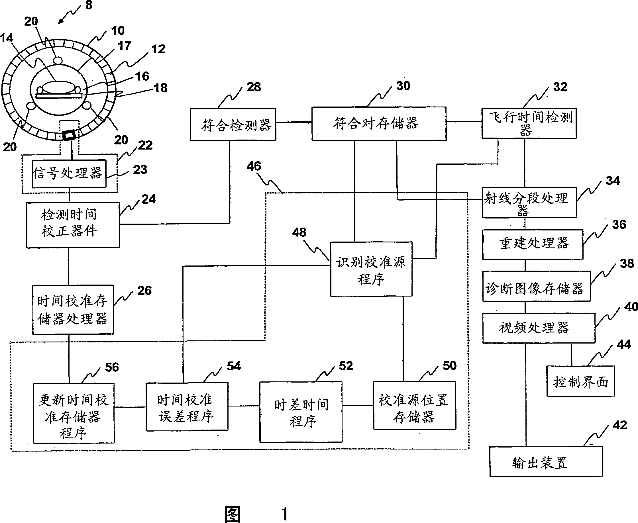
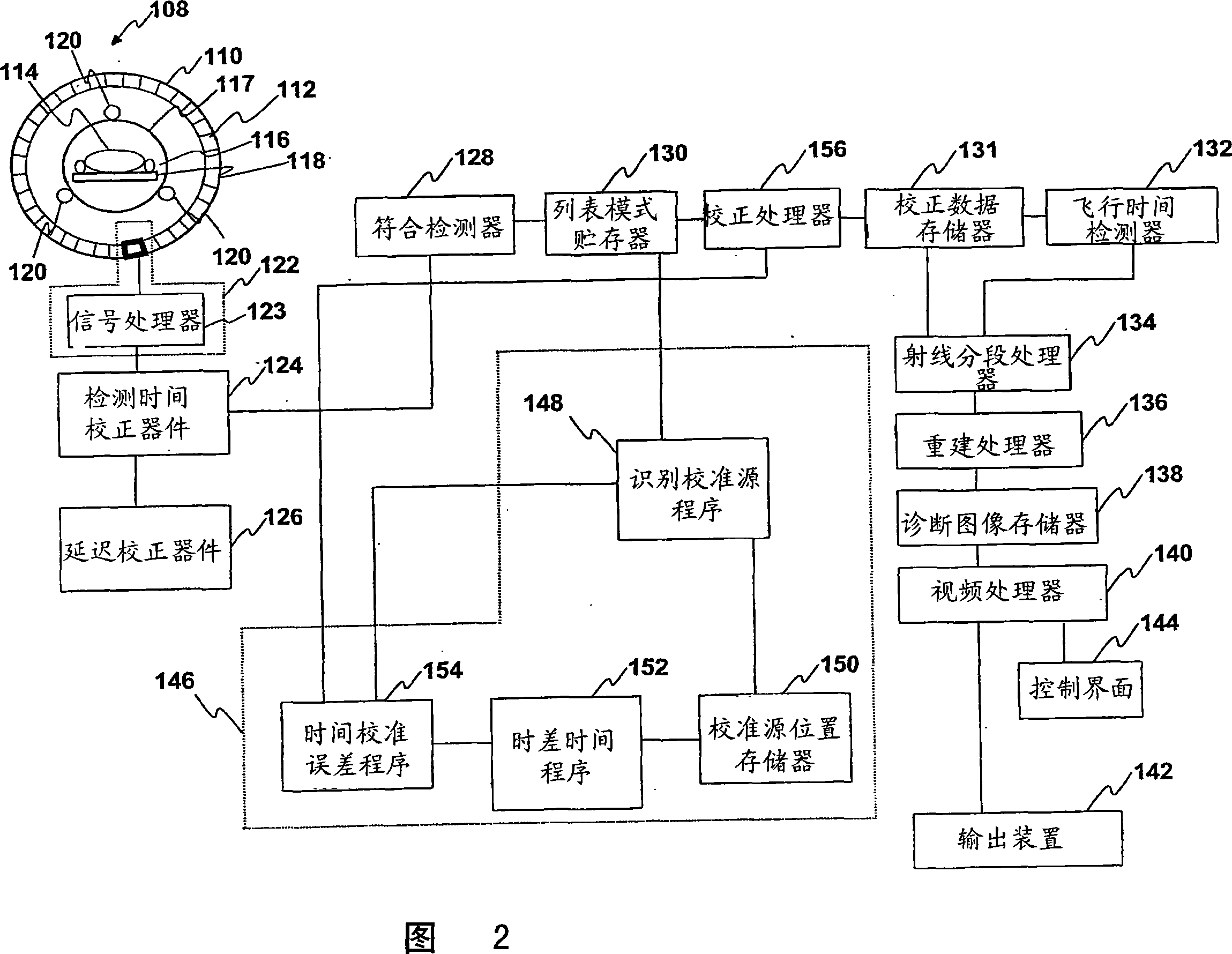
[0019] Referring to FIG. 1, the PET scanner 8 includes a cylinder 10 in which a radiation detector 12 is installed. Cylinder 10 typically has a diameter of 90 to 150 cm and a length of typically 30 to 90 cm. Preferably the radiation detector 12 is small enough to resolve the location of the received radiation within 1 to 5mm. A subject 14 to be examined is located in the central bore 16 . The aperture 16 is typically closed by a cosmetic radiotranslucent plastic cylinder 17 of about 60 to 90 cm. Subject 14 is generally received on a patient support 18 that is axially movable into and out of aperture 16 .

[0020] The subject 14 is injected with a radiopharmaceutical carrying a radioisotope which decays in a positron annihilation reaction. The radiopharmaceutical typically emits about 15 million gamma rays per second, which are detectable by detector 12 in cylinder 10 . A plurality of positron annihilation radiation sources 20 are located within the detector cylinder 10, bu...


PUM


Abstract

A cylinder (10) of radiation detectors (12) detects radiation pairs with corresponding electronic detector channels (22) which have non-uniform time-varying temporal delays. A plurality of calibration radiation sources (20) that concurrently emit radiation pairs is mounted at known positions inside of the cylinder. A temporal correction processor (46) uses the known positions of the calibration sources to determine errors in the relative detection times of radiation pairs from the calibration sources and uses the determined errors to generate corrections for the relative detection times of radiation pairs from radiopharmaceuticals injected in an imaged subject.

Description

technical field [0001] The present invention relates to the field of digital imaging. The present invention is particularly suited for use with Time Of Flight Positron Emission Tomography (TOF-PET) imaging systems and will be described with particular reference to such imaging systems. However, it will be appreciated that the present invention may also be used in positron emission tomography (PET) scanners, coincidence-capable gamma camera medical imaging systems and for temporal calibration Other types of nuclear cameras and diagnostic imaging systems. Background technique [0002] In nuclear medicine, a subject is injected with a radiopharmaceutical containing a radioisotope that decays and emits gamma radiation. Nuclear cameras detect gamma radiation and reconstruct diagnostic images that show the density of radioactive activity in a subject. [0003] During PET imaging, a positron annihilation event occurs that produces two gamma photons that are simultaneously emitte...

Claims


Application Information

Patent Timeline
IPC IPC(8): G01T1/29
CPCG01T1/2985
Inventor G·穆莱纳J·S·卡普
Owner KONINKLIJKE PHILIPS ELECTRONICS NV
Why Eureka
Try Eureka