
Method of using nuclear waste to produce heat and power

Inactive Publication Date: 2001-02-06
SNYDER STUART
View PDF11 Cites 31 Cited by
  • Summary
  • Abstract
  • Description
  • Claims
  • Application Information

AI Technical Summary

Problems solved by technology

Nuclear waste storage and disposal is a highly charged social and political issue, therefore nuclear waste often stays at temporary storage sites while interested factions debate its future.

Method used


Image

  • Method of using nuclear waste to produce heat and power
  • Method of using nuclear waste to produce heat and power

Examples


Embodiment Construction

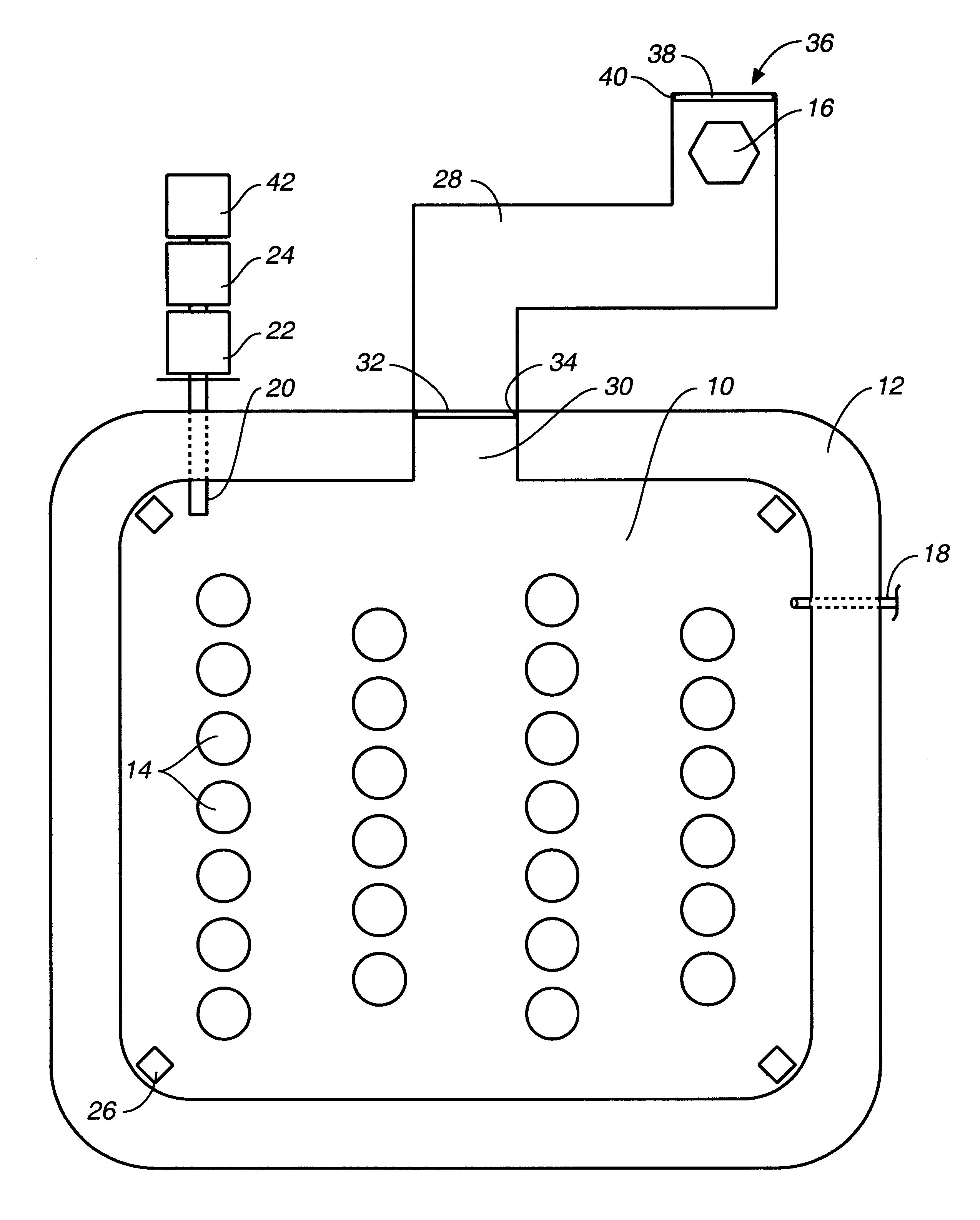
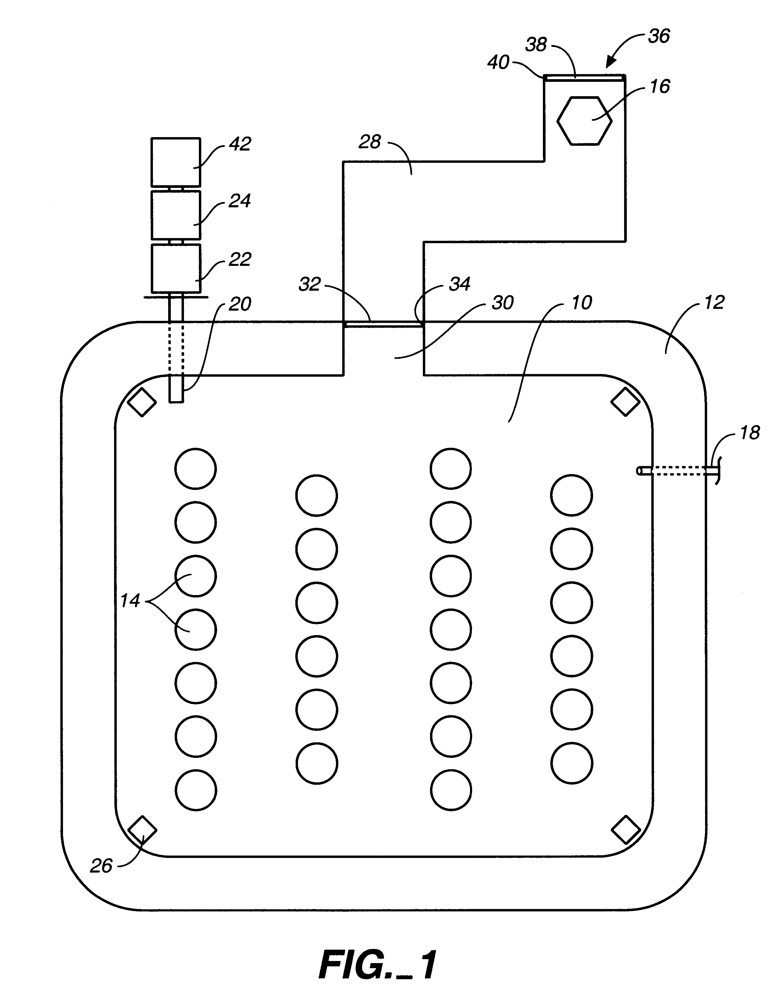
Referring to FIG. 1, a plan view of the containment room and related components of the present invention, the containment room 10 may be subterranean or above-ground. Preferably it is subterranean and lined with a concrete or earth fill wall 12 of sufficient thickness to minimize external radioactive levels according to accepted nuclear waste form engineering practices. When sealed, the room will also be gas tight. Dimensions of the containment room may be adapted to heat generation needs, disposal needs and schedules, rates of waste production, and monitoring capabilities, but one size could be roughly twenty feet in width and breadth and have a ten to twelve foot ceiling height.

Preliminary to placement in room 10, radioactive waste may be stored in long-life containers 14 in the form of columns. It is well known that radioactive waste in solution may be evaporated until radioactive products are in the solid state. The solid products may be heated to maximize oxide production, and ...


PUM


Abstract

A method of using nuclear waste material and exploiting heat generated by radioactive decay of said radioactive waste, comprising the steps of incorporating solid nuclear waste into glass, ceramic, or cementitious blocks, covering the blocks in heat absorbing sealed containers, placing the sealed containers in a columnar arrangement in a gas tight containment room, circulating a heat exchange gas around said containers, passing the heated gas through a sealed heat exchanger, and using the heated water for useful work.

Description

1. Field of the InventionThe present invention relates to a method for using nuclear waste to produce heat and / or power.2. Description of the Prior ArtMost countries using nuclear production reactors dispose of radioactive fission waste products by depositing the radioactive material in subterranean vaults or underground rock formations, well below the earth's surface and a safe distance from any moving water source. Storage vaults may comprise deep vertical wells or horizontal tunnel corridors with tunnel rooms extending laterally from the corridors. The latter method is taught in Crichlow U.S. Pat. No. 5,850,614. Prior to deposition in vaults, the waste may be mixed with materials and converted into solid form having high chemical and structural stability. For example, radioactive oxides can be melted into a borosilicate glass or, alternatively, a lead iron phosphate glass, as taught by Boatner et al U.S. Pat. No. 4,847,008, or a polymeric phosphate glass, as taught in Ropp U.S. P...

Claims


Application Information

Patent Timeline
IPC IPC(8): G21F5/005G21F9/34F27D17/00
CPCG21F5/005G21F9/34F27D17/004G21Y2002/60G21Y2004/40G21Y2004/60
Inventor SNYDER, STUART
Owner SNYDER STUART
Learn More