Display device, its manufacturing method, and display medium

A display device and display unit technology, applied in optics, instrumentation, nonlinear optics, etc., can solve problems that hinder power consumption reduction, microcapsules reduce image quality, and diffuse

Inactive Publication Date: 2008-01-23
DAI NIPPON PRINTING CO LTD
View PDF5 Cites 10 Cited by
  • Summary
  • Abstract
  • Description
  • Claims
  • Application Information

AI Technical Summary

Problems solved by technology

[0004] However, the conventional display devices disclosed in JP-A-2002-357853 and JP-A-2002-333643 have the problem that it is difficult to arrange the microcapsules without defects, and the image quality is degraded.
[0005] In addition, in the conventional display devices disclosed in International Publication WO 2004/104670, International Publication WO 2004/068208, and International Publ

Method used


Image

  • Display device, its manufacturing method, and display medium
  • Display device, its manufacturing method, and display medium
  • Display device, its manufacturing method, and display medium

Examples


Embodiment approach 1

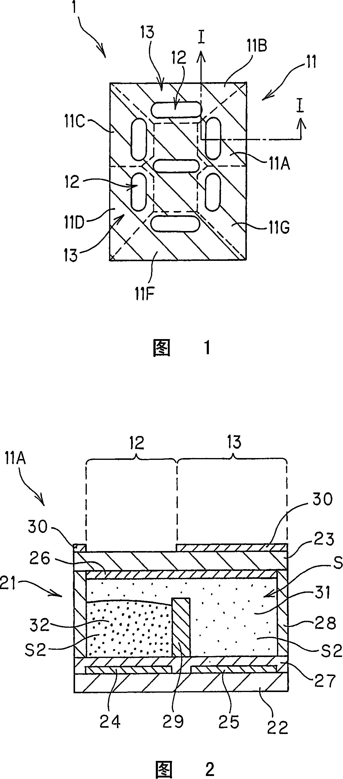
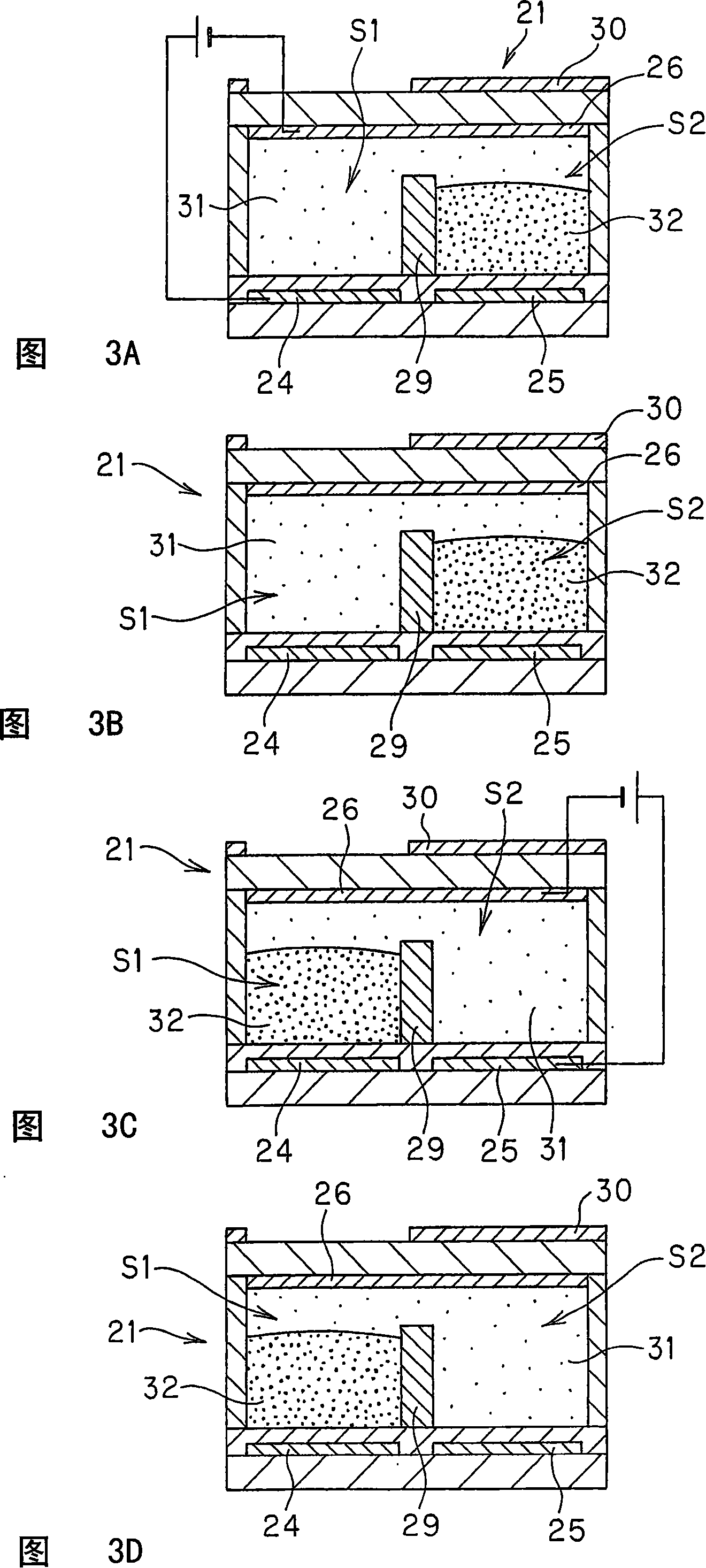
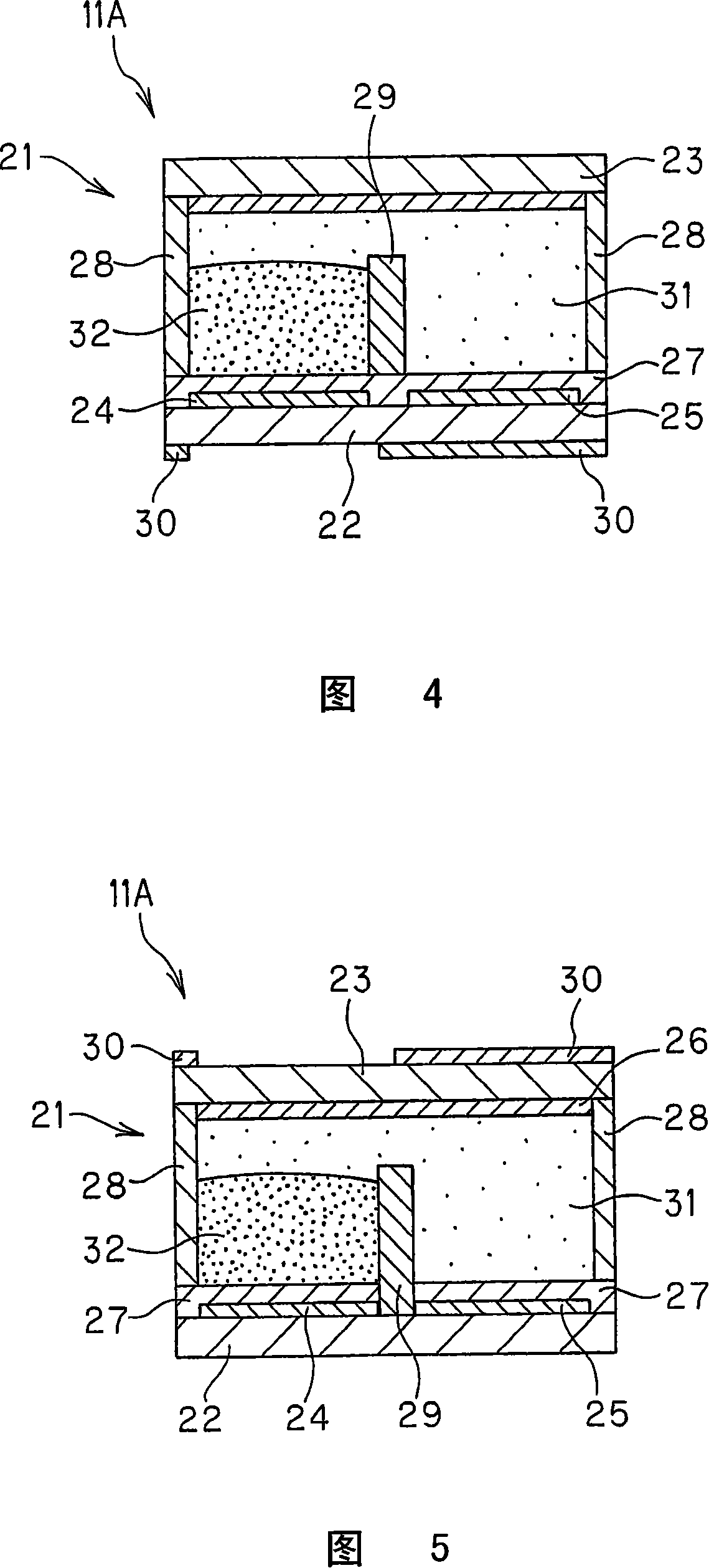
[0128] 2 is an enlarged longitudinal sectional view showing Embodiment 1 of the display device of the present invention, showing the configuration of one display unit along the line I-I in FIG. 1 . As shown in FIG. 2 , the display unit 11A encloses a conductive or polar first liquid 31 and a hydrophobic second liquid 32 in a container 21 . In addition, although the structure of the display unit 11A is shown in FIG. 2, the structure of each other display unit is the same.

[0129] The container 21 is provided with one set of base materials 22, 23; One base material 22 includes a first A electrode 24 and a first B electrode 25 arranged electrically independently from each other on the side of the liquid filling space S, and an insulating layer 27 covering them. On the insulating layer 27 , an intermediate partition wall 29 is arranged so as to be located at a boundary portion between the first A electrode 24 and the first B electrode 25 . In addition, the other base material 2...

Embodiment approach 2

[0149] FIG. 6 is a view corresponding to FIG. 2 showing Embodiment 2 of the display device of the present invention, and shows the configuration of one display unit. In the form shown in FIG. 6 , a conductive or polar first liquid 31 and a hydrophobic second liquid 32 are enclosed in a container 41 of a display unit 11A.

[0150] The container 41 is provided with one set of base materials 42, 43; One base material 42 includes, on the side of the liquid filling space S: a first A electrode 44 and a first B electrode 45 arranged electrically independently from each other; and an insulating layer 47 covering both. On the insulating layer 47, an intermediate partition wall 49 is arranged so as to be located at a boundary portion between the first A electrode 44 and the first B electrode 45, and divides the liquid filling space S. As shown in FIG. In addition, the other base material 43 is provided with the second electrode 46 on the side of the liquid filling space S, and the oth...

Embodiment approach 3

[0166] FIG. 9 is a diagram corresponding to FIG. 2 showing Embodiment 3 of the display device of the present invention, showing the configuration of one display unit. In the form shown in FIG. 9 , a conductive or polar first liquid 31 and a hydrophobic second liquid 32 are sealed in the container 61 of the display unit 11A.

[0167] The container 61 is provided with one set of base materials 62, 63; One base material 62 is provided with the 1st A electrode 64 arrange|positioned at the liquid filling space S side, and the insulating layer 67 which covers it. In addition, the other base material 63 includes a first B electrode 65 arranged on the liquid filling space S side and an insulating layer 67 covering it. In addition, a second electrode 66 is provided, arranged substantially parallel to the first A electrode 64 and the first B electrode 65 , and divides the liquid sealing space S. The second electrode 66 has a plurality of through-holes 66a serving as liquid flow paths,...


PUM

PropertyMeasurementUnit
Surface tensionaaaaaaaaaa
Opening widthaaaaaaaaaa
Thicknessaaaaaaaaaa

Abstract

A display device includes at least one display cell having at least a first electrode, a second electrode, and a vessel containing, in a sealed way, a first liquid and a second liquid which will no be mixed. The first electrode or the second electrode is electrically insulated from the first liquid and the second liquid. The first liquid has conductivity or polarity. By applying voltage to one or both of the first electrode and the second electrode so as to change the position of the first liquid and the second liquid for display. Even after stop of voltage application at the position where the first liquid and the second liquid have moved, the positions of the first liquid and the second liquid are held so as to exhibit memory characteristic.

Description

technical field [0001] The present invention relates to a display device using electrophoresis, a manufacturing method thereof, and a display medium using the display device, and more particularly, to a display device capable of maintaining a display state even after a voltage application is stopped, a manufacturing method thereof, and a display medium. Background technique [0002] In recent years, a display device has been developed in which a microcapsule (microcapsule) containing electrophoretic particles and a dispersion medium is sandwiched between two electrodes as an electrophoretic display element, and the electrophoretic particles are generated by applying a voltage to the electrophoretic display element. A phenomenon in which capsules undergo electrophoresis toward electrodes having different polarities (JP-A-2002-357853 and JP-A-2002-333643). In this display device, color display can be performed by using microcapsules of different colors in which the dispersion ...

Claims


Application Information

Patent Timeline
IPC IPC(8): G02F1/167G02B26/02G02F1/17
Inventor 池上佳奈美赤田正典
Owner DAI NIPPON PRINTING CO LTD
Why Eureka
Try Eureka