Long material laser cutting machine

A technology of laser cutting machine and laser cutting head, which is applied in the field of cutting machinery and long material laser cutting machine, can solve the problems of inaccurate arrival of pipes, waste of manpower and material resources, and low transportation efficiency, so as to save equipment space, liberate manpower, store The effect of convenient feeding

Active Publication Date: 2021-10-26
广东博特激光科技有限公司
View PDF10 Cites 1 Cited by
  • Summary
  • Abstract
  • Description
  • Claims
  • Application Information

AI Technical Summary

Problems solved by technology

[0002] The cutting machine can cut the pipe into a specified length according to the requirements. For higher processing requirements, a laser cutting machine is often used, which can not only implement complex processing paths, but also improve processing efficiency and quality; on the processing line of the existing cutting machine, due to The length of the production line is limited, and it is necessary to set up a storage rack to convert the lengthy conveying line into a multi-row side-by-side storage space. However, the existing storage rack only has a material storage function, and the feeding basically relies on manpower or semi-automatic machinery, and the transportation efficiency is low. ;There is usually an adjustment mechanism on the transportation line to ensure the level of each part of the material. The existing adjustment mechanism adjusts the height of the mechanism through a rack, which has a complex structure and high maintenance costs; at the cutting position, the pipe needs to follow the rotation of the clamping mechanism. , the traditional feeding mechanism cannot meet the requirements of use; due to factors such as errors in various parts of the equipment, the pipe often cannot reach the processing position accurately, and the chips generated during the cutting process are scattered everywhere, making it difficult to clean up; after the pipe processing is completed, the finished pipe and material The heads will be mixed together, and they need to be sorted later, which wastes manpower and material resources

Method used


Image

  • Long material laser cutting machine
  • Long material laser cutting machine
  • Long material laser cutting machine

Examples


Embodiment Construction

[0046] The following will clearly and completely describe the technical solutions in the embodiments of the present invention with reference to the accompanying drawings in the embodiments of the present invention. Obviously, the described embodiments are only some, not all, embodiments of the present invention. Based on the embodiments of the present invention, all other embodiments obtained by persons of ordinary skill in the art without making creative efforts fall within the protection scope of the present invention.

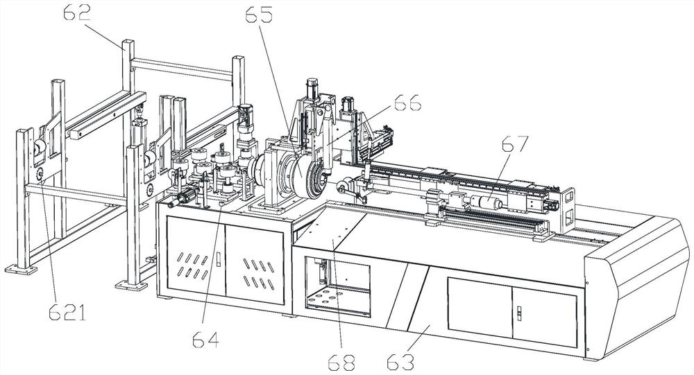
[0047] Such as figure 1 Shown: Long material laser cutting machine, including adjustable storage and feeding frame 62, machine table 63, releasable feeding mechanism 64, rotating clamping mechanism 65, laser cutting head 66, fixed-length slag discharge mechanism 67 and material distribution Mechanism 68, the adjustable storage and feeding frame 62 is located at the front end of the machine platform 63, the feed mechanism 64, the rotating clamping mechanism 6...


PUM


Abstract

The invention discloses a long material laser cutting machine. The long material laser cutting machine comprises an adjustable material storing and feeding frame, a machine table, a feeding mechanism capable of being loosened, a rotary clamping mechanism, a laser cutting head, a fixed-length slag discharging mechanism and a material distributing mechanism, wherein the adjustable material storing and feeding frame is located at the front end of the machine table, the feeding mechanism capable of being loosened, the rotary clamping mechanism and the fixed-length slag discharging mechanism are sequentially fixed to the machine table, the laser cutting head is located between the rotary clamping mechanism and the fixed-length slag discharging mechanism, and the material distributing mechanism is located below the laser cutting head. The long material laser cutting machine is adjustable in multiple positions, easy to operate, high in practicability, more convenient to store and feed, more flexible in pipe feeding process control and higher in machining precision and efficiency, and meanwhile has the functions of slag discharging, sorting and the like.

Description

technical field [0001] The invention relates to a cutting machine, especially a long material laser cutting machine, which belongs to the field of cutting machinery. Background technique [0002] The cutting machine can cut the pipe into a specified length according to the requirements. For higher processing requirements, a laser cutting machine is often used, which can not only implement complex processing paths, but also improve processing efficiency and quality; on the processing line of the existing cutting machine, due to The length of the production line is limited, and it is necessary to set up a storage rack to convert the lengthy conveying line into a multi-row side-by-side storage space. However, the existing storage rack only has a material storage function, and the feeding basically relies on manpower or semi-automatic machinery, and the transportation efficiency is low. ;There is usually an adjustment mechanism on the transportation line to ensure the level of e...

Claims


Application Information

Patent Timeline
Patent Type & Authority Applications(China)
IPC IPC(8): B23K26/38B23K26/70
CPCB23K26/38B23K26/70Y02P70/10
Inventor 唐虎
Owner 广东博特激光科技有限公司
Why Eureka
Try Eureka