Spacing mechanical arm modularization joint

A technology of modular joints and space manipulators, used in manipulators, manufacturing tools, joints, etc., can solve the problems of large output torque per unit mass, inability to meet low power consumption, large volume, etc., to achieve large output torque per unit mass, avoid Evaporation and intrusion of external dust, the effect of a high degree of integration

Inactive Publication Date: 2008-01-30
HARBIN INST OF TECH
View PDF1 Cites 34 Cited by
  • Summary
  • Abstract
  • Description
  • Claims
  • Application Information

AI Technical Summary

Problems solved by technology

[0003] The purpose of the present invention is to provide a space manipulator modular joint, which can solve the existing space manipulator modular joint, because its driving device and control device are integrated i

Method used


Image

  • Spacing mechanical arm modularization joint
  • Spacing mechanical arm modularization joint
  • Spacing mechanical arm modularization joint

Examples


specific Embodiment approach 1

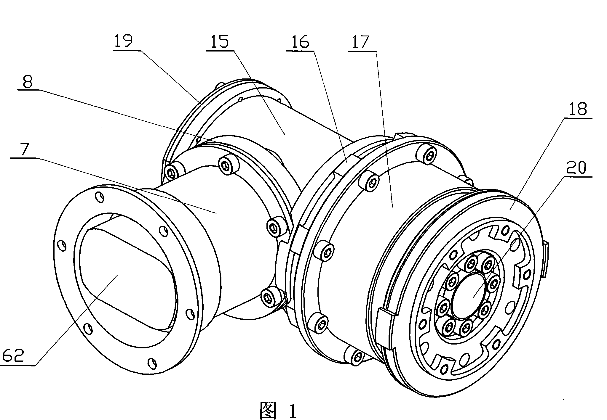
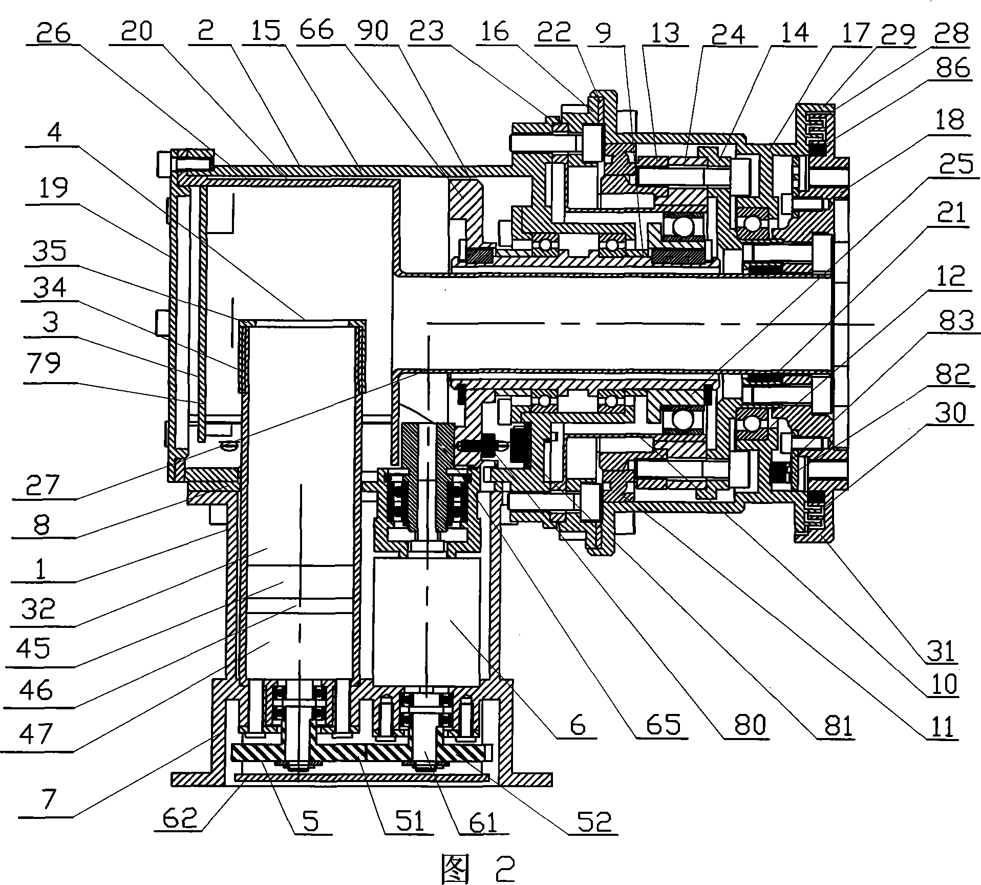
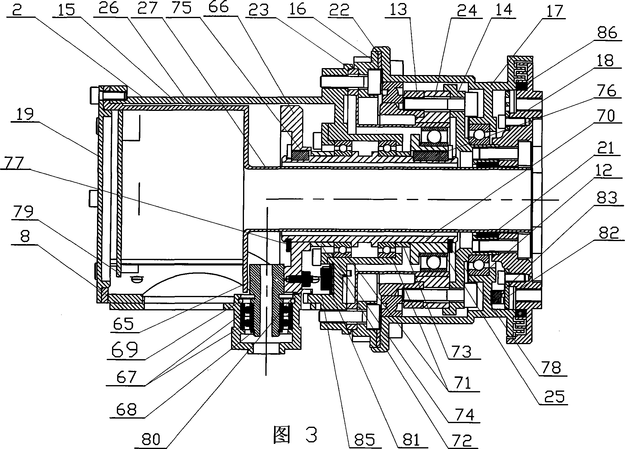
[0007] Specific Embodiment 1: This embodiment is described in conjunction with FIGS. 1 to 17. This embodiment is composed of an input device 1, an output device 2, and an electrical device 3; the input device 1 is composed of a drive device 4, a gear device 5, and a planetary reducer. 6. The input device housing 7 is composed of an adapter flange 8; the output device 2 includes a crown gear device 90, a hollow transmission shaft device 9, a harmonic reducer 10, a large thin-walled bearing 11, a small thin-walled bearing 12, Large thin-wall bearing inner ring support seat 13, small thin-wall bearing inner ring support seat 14, first shell 15, intermediate connecting flange 16, second shell 17, output flange 18, joint rear end cover 19, sleeve 20. Isolation support ring 21 and adjusting gasket 22; the harmonic speed reducer 10 is made up of a flexible spline 23, a rigid spline 24 and a wave generator 25, and the sleeve 20 is made of an integrated big end sleeve 26 and The small ...

specific Embodiment approach 2

[0010] Specific Embodiment 2: This embodiment is described in conjunction with Fig. 2, Fig. 4 and Fig. 6. The drive device 4 of this embodiment consists of a DC brushless motor 32, a friction reverse brake 33, a motor sleeve 34 and a motor sleeve cover 35 Composition; the output end of the DC brushless motor 32 is connected to the input end of the friction type reverse brake 33, the output end of the friction type reverse brake 33 is connected to the input end of the gear device 5, and the DC brushless motor 32 and The friction type reverse brake 33 is contained in the motor sleeve 34, and the rear end of the motor sleeve 34 is threadedly connected with the motor sleeve cover 35. Such setting has the advantages of simple structure and stable and reliable transmission. The friction reverse brake works normally in forward transmission and self-locking in reverse transmission, and does not consume power during braking. Other components and connections are the same as those in the...

specific Embodiment approach 3

[0011]Specific embodiment three: This embodiment is described in conjunction with Fig. 2, Fig. 5 and Fig. 6. The friction reverse brake 33 of this embodiment is composed of a bearing backing plate 36, a pin shaft 37, a bearing 38, a pin shaft plate 39, and a friction plate. 40. Friction plate 2 41, output gear 42, output gear sleeve 43, output gear sleeve bearing 44, brake first housing 45, brake second housing 46 and brake third housing 47; the brake first housing 45, brake The second casing 46 and the third casing 47 of the brake are sequentially connected in series and installed in the motor sleeve 34, the bearing backing plate 36 is installed in the first casing 45 of the brake, and the pin plate 39 is installed in the second casing 46 of the brake and the third casing of the brake. Between 47, three pin holes 48 are evenly distributed along the circumferential direction at corresponding positions on the bearing backing plate 36 and the pin plate 39, and the bearing backing...


PUM


Abstract

A space manipulator modularization arthrosis relates to a space manipulator arthrosis. The invention aims at the problems of the prior space manipulator modularization arthrosis of large volumes, large masses and large powers. A drive device (4) is connected with a planetary reducer (6) by a gear device (5); the planetary reducer (6) is connected with a crown gear device (90) which as well as a wave generator (25) is connected with a hollow transmission shaft device (9); a first external shell (15) is fixedly connected with a flexible wheel (23), a middle connecting flange (16) and a second external shell (17); the flexible wheel (23) is arranged on the hollow transmission shaft device (9) which is sleeved on a small-end sleeve (27); large and small thin-wall bearings are arranged between large and small thin-wall bearing internal ring supporting seat and the second external shell (17); a labyrinth-typed sealing structure and a mechanical position limit structure are arranged between the second external shell (17) and an output flange disc (18). An electric device (3) is fixedly arranged in the output device (2). The invention has the advantages of small volume, light mass, low powder consumption, and meeting the performance requirement of the space manipulator modularization arthrosis of low power consumption, large output moment and high reliability.

Description

technical field [0001] The invention relates to a space manipulator joint. Background technique [0002] In the past 10 or 20 years, my country's space technology has developed rapidly. In the future, my country will build its own space station in space, and space robots will be required to perform tasks such as the construction and maintenance of space stations, the release, maintenance and recovery of satellites. However, at present, space robots It is not yet possible to complete these tasks. In the near future, our country will explore the moon, Mars and even other celestial bodies, and some operations in space are required, and these operations are inseparable from the space robotic arm. The modular joint is an important part of the space manipulator. The performance of the modular joint determines the reliability of the whole manipulator, the end output torque, the end position accuracy and other main performances. The joint structure of the space robot developed by t...

Claims


Application Information

Patent Timeline
IPC IPC(8): B25J17/00B25J13/00B25J19/00
Inventor 刘宏孙奎谢宗武李德伦熊根良
Owner HARBIN INST OF TECH
Why Eureka
Try Eureka