Magnetic sensor and magnetic disk apparatus

A technology of a magnetic sensor and a storage device, applied in the field of magnetic sensors, can solve problems such as the deterioration of shielding effect and the like

Inactive Publication Date: 2008-01-30
FUJITSU LTD
View PDF2 Cites 2 Cited by
  • Summary
  • Abstract
  • Description
  • Claims
  • Application Information

AI Technical Summary

Problems solved by technology

However, when the width of the shield electrode layer is reduced, the shielding effect for shielding the magnetoresistance effect element from the magnetic flux generated from the magnetic disk deteriorates.

Method used


Image

  • Magnetic sensor and magnetic disk apparatus
  • Magnetic sensor and magnetic disk apparatus
  • Magnetic sensor and magnetic disk apparatus

Examples


Embodiment 1

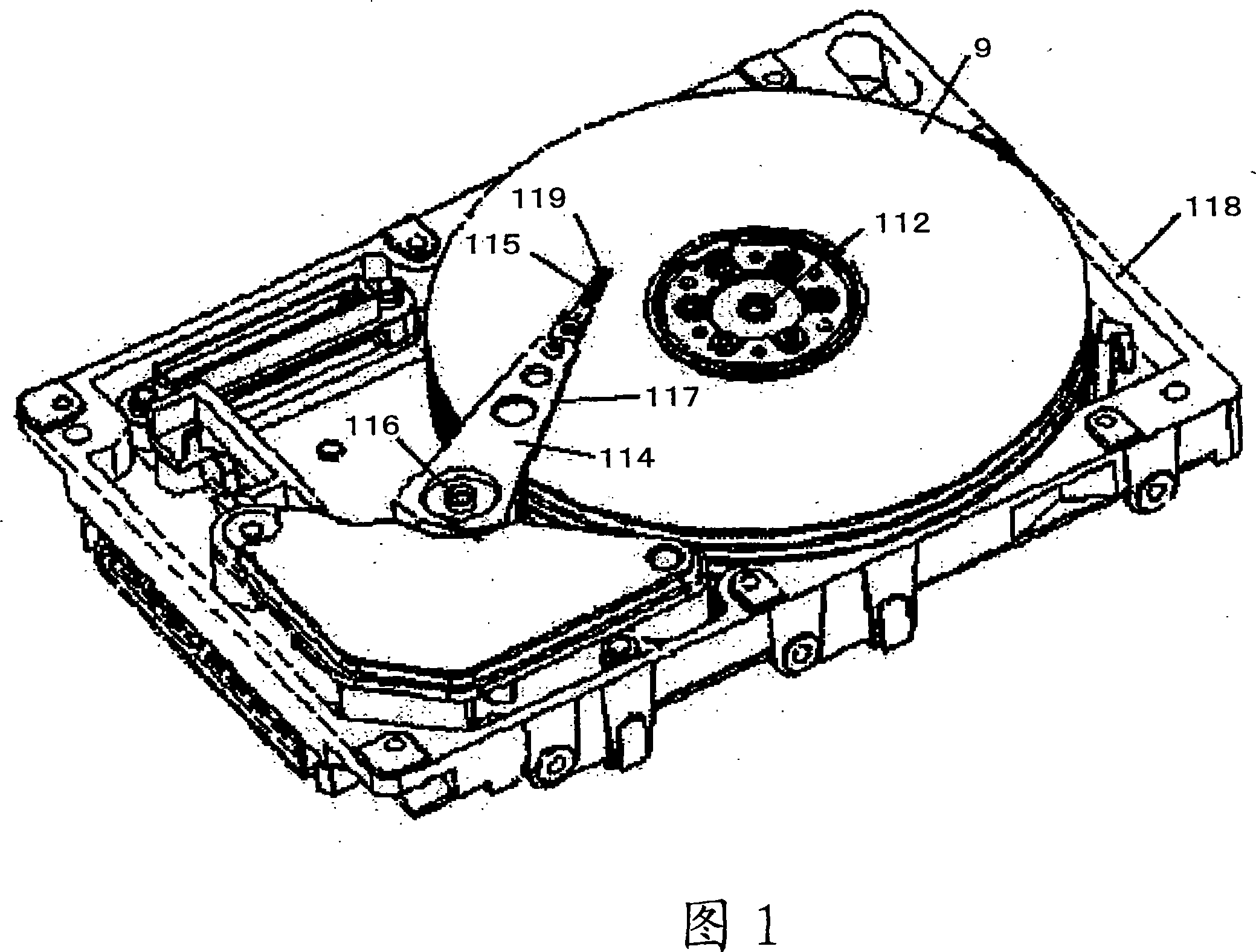
[0022] FIG. 1 is a perspective view of a magnetic disk device. The magnetic disk 9 includes magnetic information and is rapidly rotated by the spindle motor 112 . The transmission arm 114 is provided with a suspension 115 made of stainless steel. In addition, the transmission arm 116 is rotatably fixed to the housing 118 via the shaft 116 , and the transmission arm 116 moves along the radial direction of the magnetic disk 9 . Accordingly, the slider 119 mounted to the suspension 115 moves over the magnetic disk 9, thereby performing recording and reproduction of information on the track. In the housing 118, a detection circuit device for detecting a reproduced signal is fixed. The detection circuit device supplies a detection current to a magnetoresistance effect element in the reading section of the magnetic head, and measures a voltage change of the magnetoresistance effect element to reproduce information from the magnetic disk 9 .

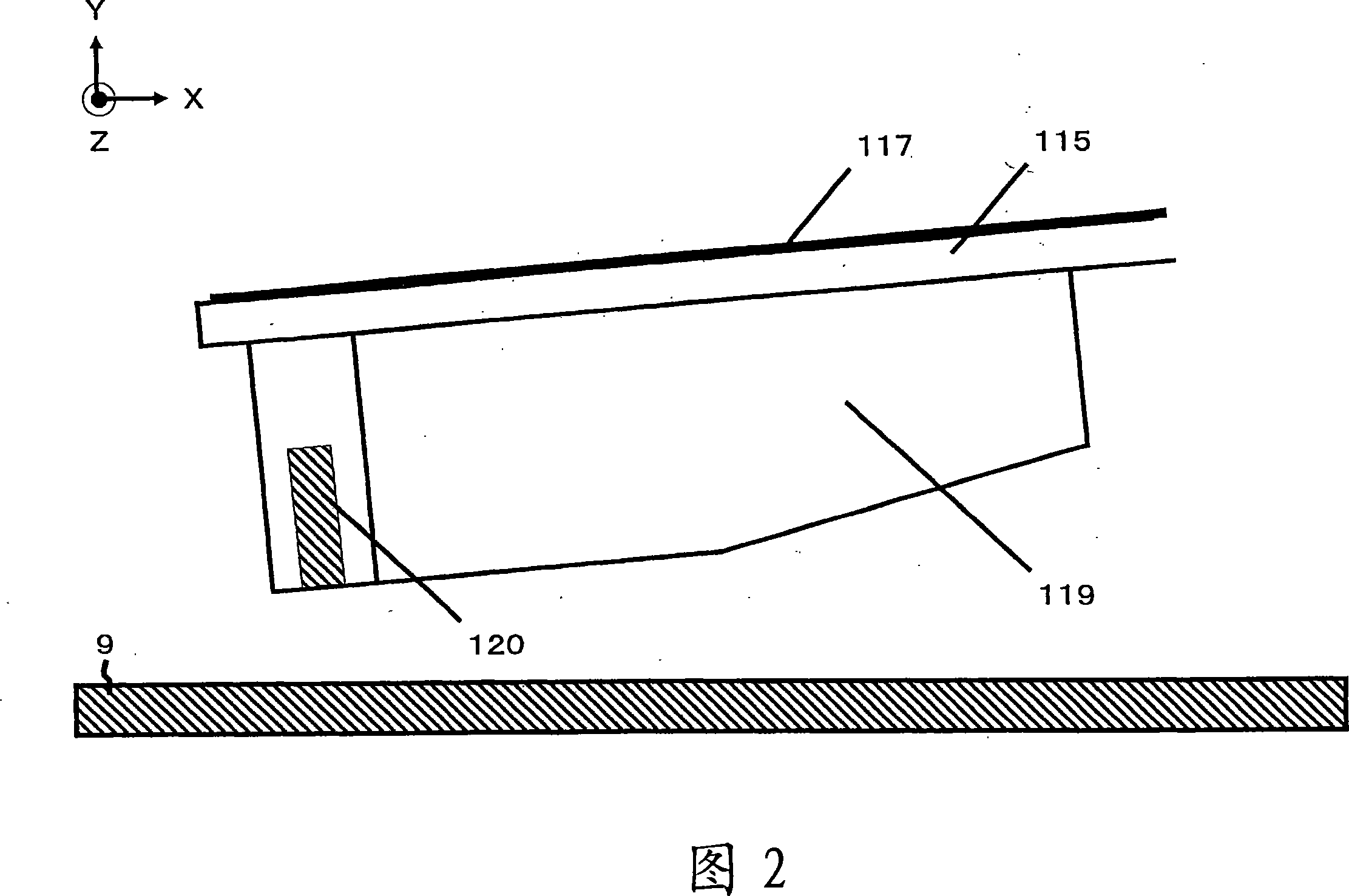
[0023] FIG. 2 is a schematic diagram ...

Embodiment 2

[0034] In Embodiment 1, a structure is described in which the lower shield electrode layer 6 and the upper shield electrode layer 4 are formed to sandwich the magnetoresistance effect element 5 in the thickness direction; however, other structures may also be formed.

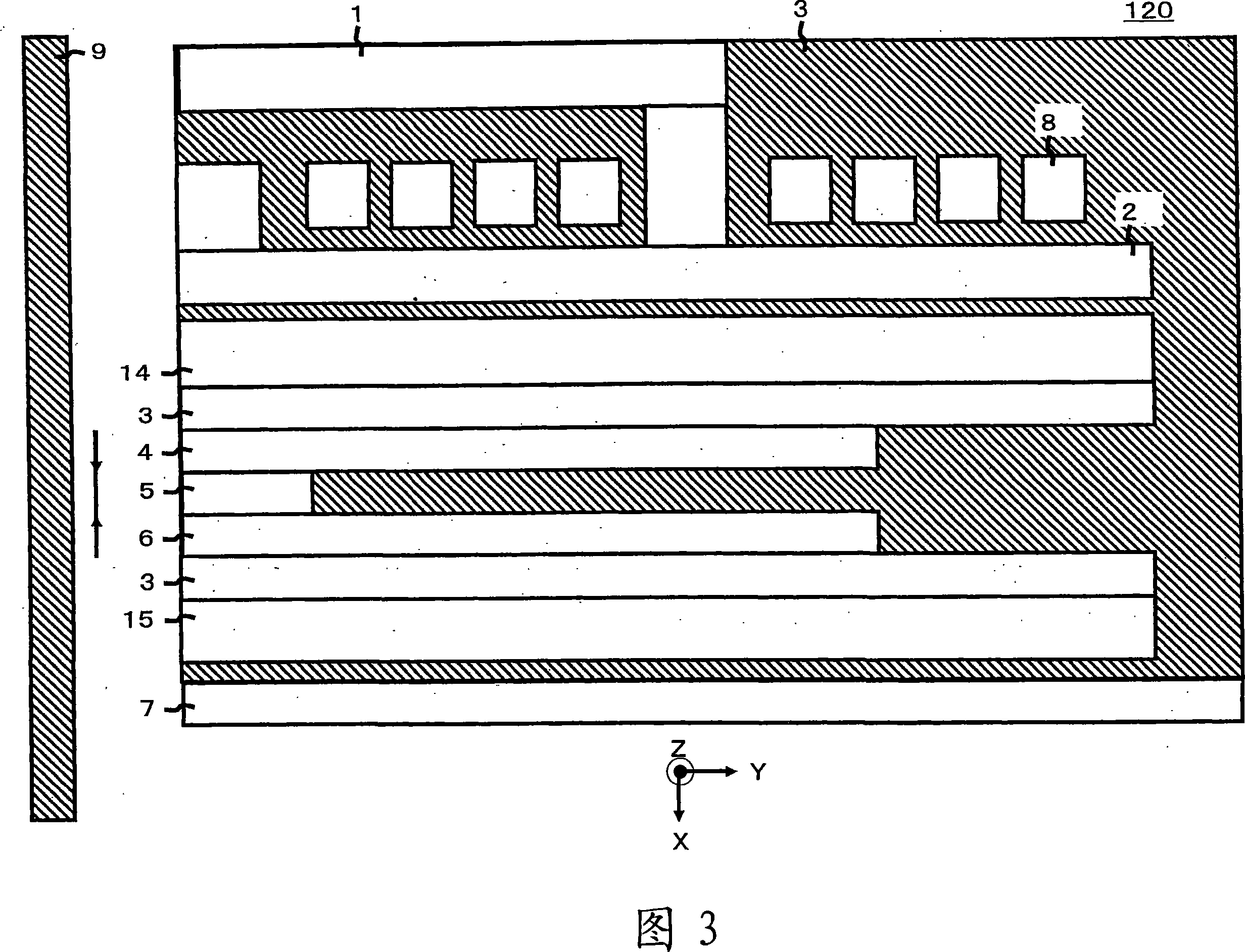
[0035] 7 is a cross-sectional view of the magnetic head 120 of Embodiment 2 taken in a direction perpendicular to the air bearing surface of the magnetic head 120 . In this magnetic head 120, the lower shield electrode layer 6 and the upper shield electrode layer 4 are formed of AlTiC (Al 2 o 3 - TiC) on the substrate 7, so that the magnetoresistance effect element 5 is sandwiched in the lamination direction. In addition, an upper shield layer 14 is formed outside the upper shield electrode layer 4 . The lower magnetic pole 2 of the write head is formed on the upper shield layer 14 , and the write coil 8 and the upper magnetic pole 1 are also formed, thereby forming the magnetic head 120 .

[0036] The lower ...


PUM

PropertyMeasurementUnit
thicknessaaaaaaaaaa

Abstract

The present invention provides a tunnel-effect type magnetoresistive head (120) which can prevent degradation of a tunnel-effect type magnetoresistive effect element caused by contact with a magnetic recording medium without degrading a shielding effect. In this tunnel-effect type magnetoresistive head (120), for the above purpose, an exposed surface area of a shield and electrode layer, which is viewed from an air bearing surface, is decreased, and a shield layer is also provided outside the shield and electrode layer.

Description

technical field [0001] The present invention relates to a magnetic sensor for reproducing magnetic information from a magnetic disk. Background technique [0002] Magnetic disk devices are required to increase their storage capacity, and the recording density of magnetic disks has been increased. In order to increase the recording density, it is necessary to reduce the area between bits of the magnetic disk to increase the number of recordable signals. However, when the area between the bits is reduced, the size of the magnet forming the area between the bits is reduced, and thus, the magnetic flux generated by the magnet is also reduced. Therefore, the magnetic flux cannot be supplied to the magnetic sensor unless the flying height of the magnetic head is lowered. [0003] When the flying height of the magnetic head is lowered, it is easy to bring the air bearing surface of the magnetic head into contact with the magnetic disk. When the air bearing surface is brought int...

Claims


Application Information

Patent Timeline
Patent Type & Authority Applications(China)
IPC IPC(8): G11B5/39
Inventor 北岛政充
Owner FUJITSU LTD
Why Eureka
Try Eureka