Electric motor with reduction gear mechanism

A reduction gear and motor technology, applied in the field of motors, can solve problems such as damage, and achieve the effect of reducing assembly steps, reducing noise, and reducing the number of parts

Active Publication Date: 2008-01-30
MITSUBA CORP
View PDF6 Cites 19 Cited by
  • Summary
  • Abstract
  • Description
  • Claims
  • Application Information

AI Technical Summary

Problems solved by technology

However, since the sliding contact portion between the brushes and the commutator in the motor generates noise, it is necessary to apply various measures to prevent the noise from causing damage to other electrical components or the like (audio noise, etc.)

Method used


Image

  • Electric motor with reduction gear mechanism
  • Electric motor with reduction gear mechanism
  • Electric motor with reduction gear mechanism

Examples


Embodiment Construction

[0048] Embodiments of the present invention will be described in detail below in conjunction with the accompanying drawings.

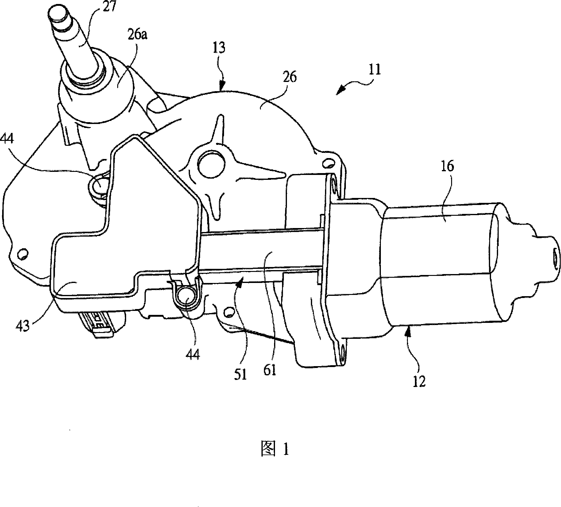
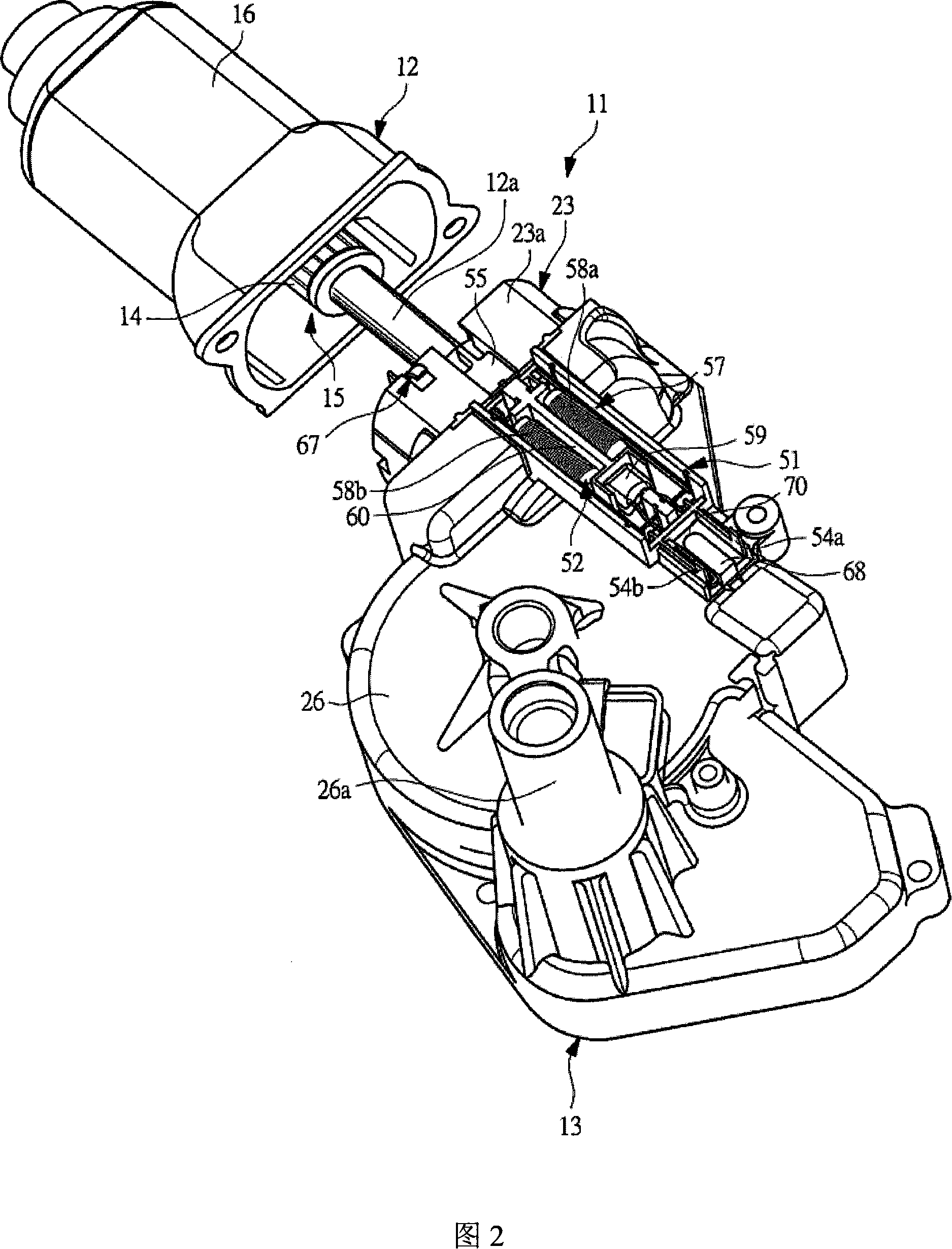
[0049] FIG. 1 is a perspective view of a wiper motor according to an embodiment of the present invention, and FIG. 2 is an exploded perspective view of the wiper motor shown in FIG. 1 .

[0050] The wiper motor 11 shown in FIG. 1 is used as a driving source of a rear wiper disposed on a vehicle as a motor having a reduction gear mechanism in which a motor main body 12 and a reduction gear device 13 are combined into a One.

[0051] As shown in Figure 2, the motor main body 12 is used as a brushed motor, and the brushed motor is configured with a rotating shaft 12a, wherein a commutator 14 and an armature iron core (not shown) are fixed on the rotating shaft 12a superior. A plurality of coils (armature coils) not shown in the figure are wound on the slots of the armature core, and the ends of the coils are respectively connected to the corresponding c...


PUM


Abstract

In an electric wiper motor with a motor body and a deceleration mechanism. A holding case is arranged on a brush holder, and the brush holder is on the motor body and the holding case is on the outer surface of a gear case, therefore a motor yoke is stuck out. A noise prevention means with a pair of chokes and a bi-directional rheostat held in the holding case and connected between a power supply terminal of a connector and brush, wherein the connector is arranged on said gear case. The noise generated by the supply circuit is absorbed by the noise prevention means and the noise leaking outside via an opening of said motor yoke is also absorbed by the noise prevention means.

Description

[0001] Cross References to Related Applications [0002] Pursuant to U.S.C. §119, this application claims Japanese Patent Application No. 2006-206459 filed on July 28, 2006, Japanese Patent Application No. 2006-206460 filed on July 28, 2006, filed on July 28, 2006 Foreign priority of Japanese Patent Application No.2006-206461 filed on June 21, 2007 and Japanese Patent Application No.2007-163460 filed on June 21, 2007 Right, the disclosure of this application is hereby incorporated by reference. technical field [0003] The present invention relates to a motor with a reduction gear mechanism, which includes a motor main body having a rotating shaft and a reduction gear mechanism for reducing the rotation speed of the rotation shaft and outputting the rotation speed through an output shaft. Background technique [0004] An electric motor driven by a power source such as a battery mounted on a vehicle is generally used as a drive source for a wiper device, a power window devic...

Claims


Application Information

Patent Timeline
Patent Type & Authority Applications(China)
IPC IPC(8): H02K5/22H02K13/00H02K23/66H02K23/68
Inventor 神田哲羽鸟周一
Owner MITSUBA CORP
Why Eureka
Try Eureka