Arrestor and method of measuring leakage current of arrestor

A lightning arrester and lightning protection technology, which is applied in the field of lightning arresters, can solve the problems of increasing the size of the insulating cap 310, and achieve the effects of size reduction, easy leakage current, and weight reduction

Active Publication Date: 2008-01-30
JAPAN AE POWER SYST +1
View PDF1 Cites 2 Cited by
  • Summary
  • Abstract
  • Description
  • Claims
  • Application Information

AI Technical Summary

Problems solved by technology

Thus, the difficulty is that the insulating cap 310 would be enlarged more than necessary

Method used


Image

  • Arrestor and method of measuring leakage current of arrestor
  • Arrestor and method of measuring leakage current of arrestor
  • Arrestor and method of measuring leakage current of arrestor

Examples


no. 1 approach

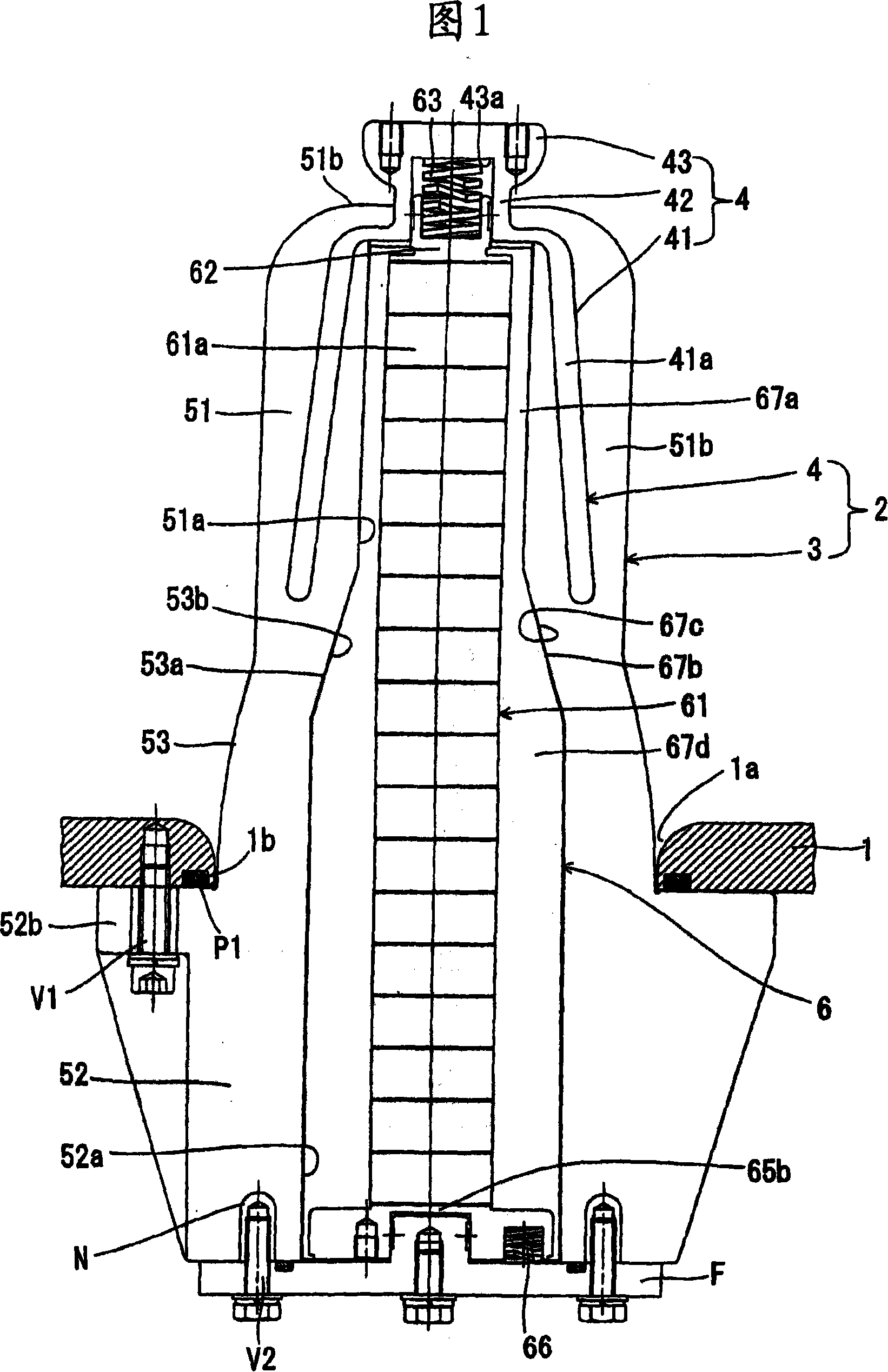
[0087] The partial sectional view in Fig. 1 shows an example of the arrester of the present invention, which belongs to the 66 / 77 kV class.

[0088] In this drawing, the electrical equipment with the lightning arrester of the present invention includes an equipment housing 1, which hermetically accommodates electrical equipment such as switches (not shown in the figure). And, an insulating gas such as SF6 or the like is charged into the device case 1 . In addition, an opening portion 1a is provided at the bottom of the device case 1, and the sleeve 2 is installed into the opening portion 1a so that the top end of the sleeve 2 itself is located inside the device case 1, and the sleeve 2 itself The rear end hermetically covers the opening portion 1a. A formed lightning protection element stack 6 is detachably installed in the sleeve 2 , wherein the formed lightning protection element stack 6 has a lightning protection element stack 61 which will be mentioned below.

[0089] The ...

no. 2 approach

[0108] Fig. 4 is a partial sectional view of a lightning arrester according to a second embodiment of the present invention. Meanwhile, in the drawings, the same reference numerals are used to designate those parts that are the same as the corresponding parts in FIG. 1, and detailed descriptions are omitted.

[0109] In this embodiment, by making the sleeve 2 from an insulating material such as epoxy resin, a current cut-off area Z can be formed at the rear end of the sleeve 2 leading to the outside of the device housing 1 . Specifically, the current cut-off area Z is located at a portion extending from the end face of the rear end of the lower cylindrical portion 52 as an insulating cylindrical member toward the outer wall of the device case 1 .

[0110] For the lightning arrester of this structure, on the outside of the equipment housing 1, the grounding conductor E is installed in the current cut-off area Z located at the rear end of the sleeve 2—that is, by stacking the li...

no. 3 approach

[0113] Fig. 5(a) is a partial sectional view of the lightning arrester according to the third embodiment of the present invention, and the top view in Fig. 5(b) shows the sealing cover in this embodiment. Meanwhile, in the drawings, the same reference numerals are used to designate those parts that are the same as the corresponding parts in FIG. 1, and detailed descriptions are omitted.

[0114] In Fig. 5 (a), the formed lightning protection element stack 6 has: a lightning protection element stack 61 formed by stacking a plurality of lightning protection elements, wherein the lightning protection element uses zinc oxide as a main component; a joint conductor 62, which is installed to the lightning protection element stack 61 on the top end side (high voltage side); a cylindrical pressure metal fitting 64, which is mounted to the rear end side (low voltage side) of the lightning protection element stack 61; and a molded insulator 67d made of a material such as silicon rubber T...


PUM


Abstract

An arrestor provides a bushing (2) installed in an opened section (1a) of an equipment case (1) hermetically, and a molded arrestor elements stack (6) of this invention is installed in the bushing (2) removably. The bushing (2) provides a rigid, insulated bushing body (3) and a high-voltage shielding electrode (4) embedded in the tip of the bushing body (3) concentrically with the bushing body (3). The bushing body (3) provides an intermediate cylindrical section (53) having a tapered insertion hole (53a) and the high-voltage shielding electrode (4) provides a shielding body (41). The molded arrestor elements stack (6) provides an arrestor elements stack (61) comprising a layer stack of a plurality of arrestor elements (61a) containing zinc oxide as the main component, and a molded rubber (67) comprising silicone rubber and so on is provided at the circumference of the arrestor elements stack (61).

Description

technical field [0001] The invention relates to a lightning arrester. More specifically, the present invention relates to a lightning arrester having a laminated body (hereinafter referred to as "lightning protection element stack") composed of two or more non-linear resistance elements (hereinafter referred to as "lightning protection element"), The resistance element therein contains zinc oxide as a main component. Background technique [0002] In general, in gas-insulated switchgear installed in power stations or substations, etc., lightning arresters should be installed to protect power equipment such as switchgear or transformers, so as to prevent abnormal voltage from invading through power cables when lightning occurs. of these devices. [0003] So far, there is a lightning arrester of the type shown in FIG. 16 in the prior art (see, for example, Non-Patent Document No. 1), which has a stack of lightning protection elements 100 placed vertically into a container 110...

Claims


Application Information

Patent Timeline
IPC IPC(8): H01C7/12H02B13/02H01T1/00H02B13/065H02B3/00
CPCH01C7/12H01C7/126
Inventor 伊藤敦绵引聪史斋藤和弘岩井田武中岛昌俊汪士楠足立和久濑间信幸品川润一
Owner JAPAN AE POWER SYST
Why Eureka
Try Eureka