Machine system with a thermo-syphon cooled superconductor rotor winding

A rotor winding and machine technology, applied in the usage of superconductor elements, regenerative heat exchangers, cooling/ventilation devices, etc., can solve the problems of large heat loss, failure to meet the life requirements of shipbuilding maintenance intervals, etc., and achieve good The effect of thermal coupling

Inactive Publication Date: 2008-01-30
SIEMENS AG
View PDF2 Cites 18 Cited by
  • Summary
  • Abstract
  • Description
  • Claims
  • Application Information

AI Technical Summary

Problems solved by technology

In addition, the heat loss of such a circulation device is very high, which hardly meets the

Method used


Image

  • Machine system with a thermo-syphon cooled superconductor rotor winding

Examples


Embodiment Construction

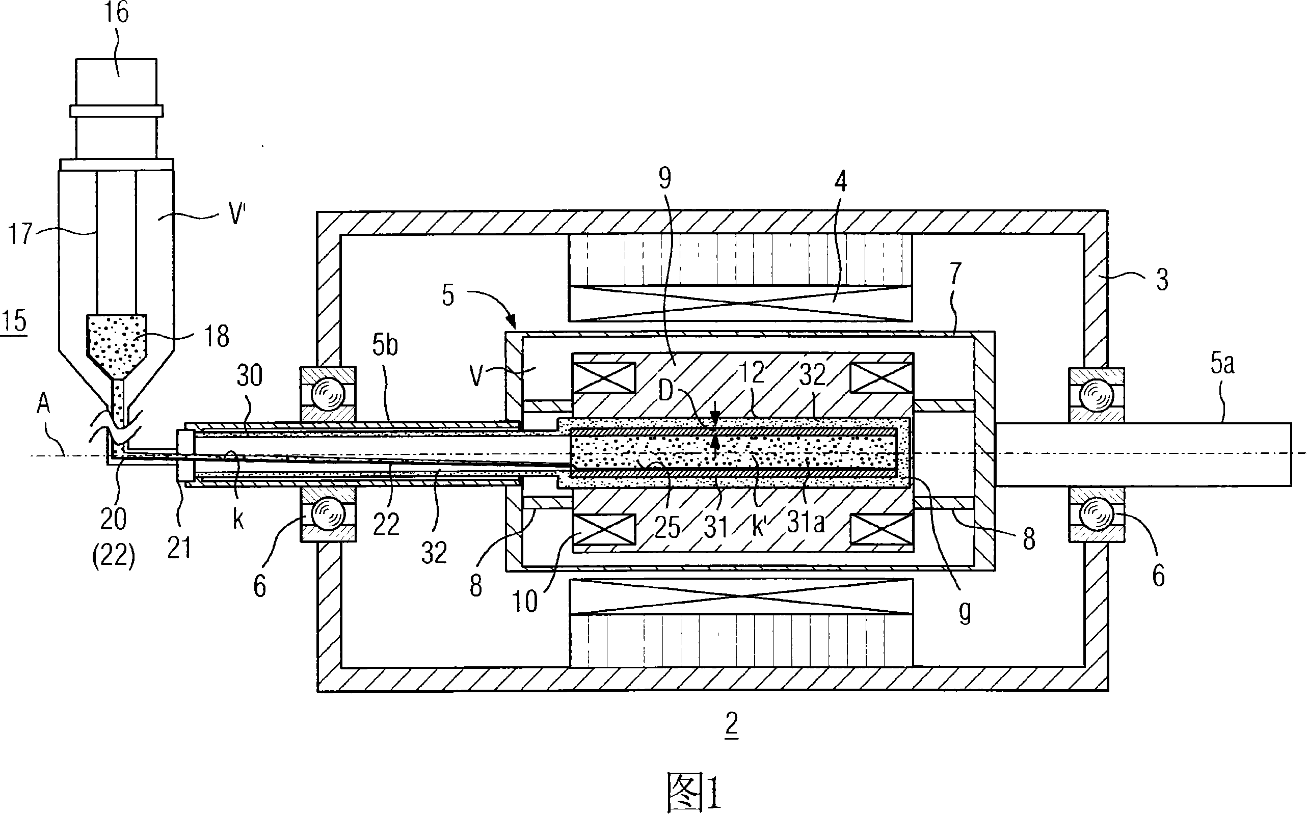
[0029] The machine system of the present invention includes a machine or an electric motor, and also includes an auxiliary cooling unit. In the embodiments described below with the aid of the figures, this machine can in particular be a synchronous motor or a generator. The machine comprises a rotating superconducting winding which can in principle be made of metallic LTS material or oxidized HTS material. The second material is preferably used in the following examples. The winding can be formed with a coil or a coil system in a 2-pole, 4-pole or other multi-pole arrangement by means of corresponding conductors. The drawing shows the basic structure of a corresponding synchronous motor, the machine system being of the embodiment disclosed in WO 02 / 15370 A1 mentioned at the outset ( FIG. 5 , in conjunction with FIGS. 2 and 3 ).

[0030] The machine indicated at 2 comprises a stationary outer casing 3 at room temperature with a stator winding 4 . A rotor 5 is surrounded by t...


PUM


Abstract

A machine has a rotor, that can be rotated about an axis, with a superconductive winding that is coupled in a heat-conducting manner to a central coolant area of a fixed heat conducting body proturding into a hollow of the rotor via a winding carrier and a heat contact gas. The coolant area forms a line system with the line parts thereof, that are laterally connected thereto, and a condenser area of a cold unit, in which a coolant circulates in the line system as result of a thermosiphon effect. To maintain the supply of coolant to the central coolant area, even when the rotor encounters difficulties, the coolant area is provided with a lining of a porous material, preferably a sinter material, having high thermal conductivity.

Description

technical field [0001] The invention relates to a machine system having [0002] a) a rotor rotatable about a rotational axis, surrounded by a stator, said rotor having at least one rotor winding, the superconductors of which are thermally coupled to an axially extending cylindrical central rotor cavity; [0003] b) a heat conductor extending fixedly into the rotor cavity and maintaining an annular gap, said heat conductor having a central coolant zone: [0004] c) a hot contact gas located within said annular gap; [0005] d) a stationary cooling unit external to said rotor, said cooling unit having a condenser zone; and [0006] e) a plurality of tubular conduit members extending between the central coolant region of the heat conductor and the condenser region of the cooling unit. [0007] In this case, the central coolant zone, the tubular pipe part and the condenser zone form a closed pipeline system in which a coolant circulates or can circulate in this pipeline system...

Claims


Application Information

Patent Timeline
IPC IPC(8): H02K55/04H02K9/20F28D17/02
CPCY02E40/625H02K55/04F28D15/02Y02E40/60
Inventor 伯恩德·格罗莫尔
Owner SIEMENS AG
Why Eureka
Try Eureka