
Hanger with steel-reel damage-proof function
A spreader and steel coil technology, applied in the spreader field, can solve the problems of resource waste, economic loss of production enterprises, breakage, etc., and achieve the effect of avoiding scratches and being scratched.
- Summary
- Abstract
- Description
- Claims
- Application Information
AI Technical Summary
Problems solved by technology
Method used
Image

Examples
Embodiment Construction
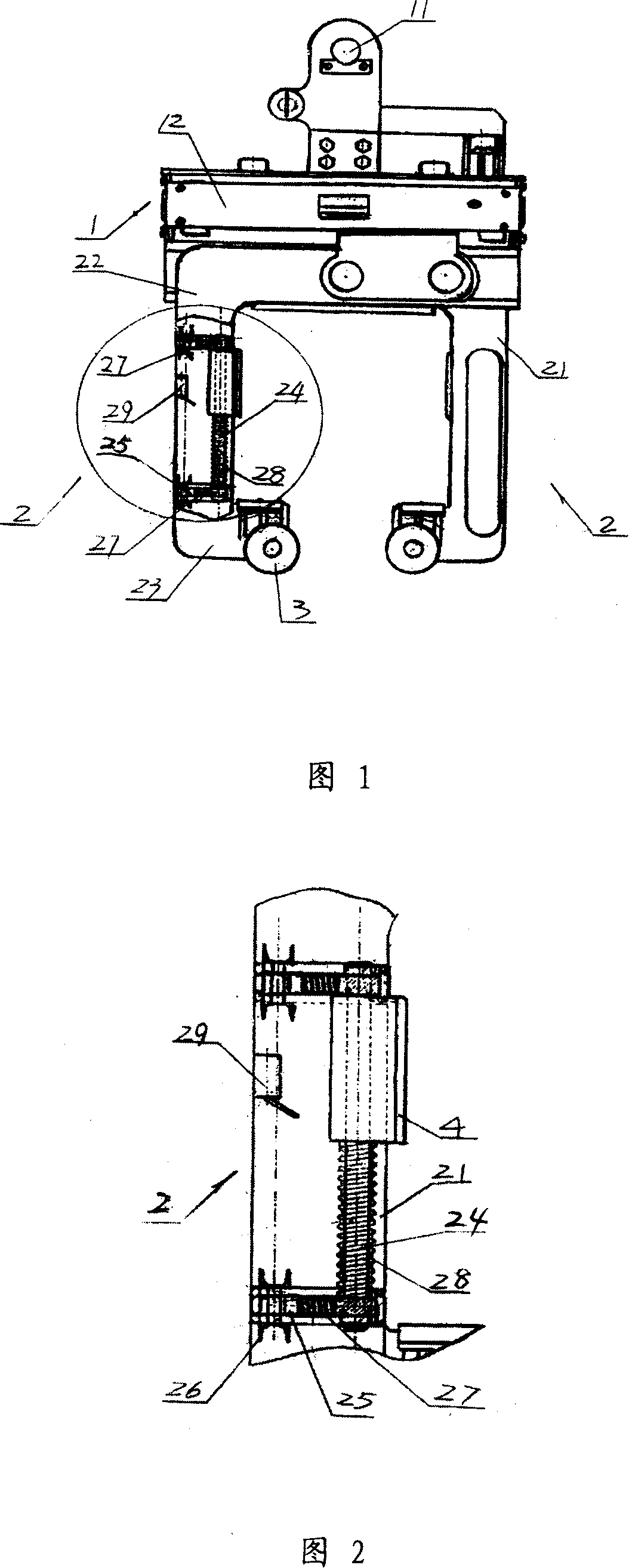
[0011] Referring to Fig. 1 and Fig. 2, these two figures show the appearance overall structure of an embodiment of the hoist with the function of preventing damage to steel coils proposed by the present invention. The spreader includes a suspension element 1 and a clamp arm 2, and a guide wheel 3 installed at the lower end of the clamp arm 2. Wherein, suspension element 1 comprises the suspension ring 11 that can be connected with the suspension hook of elevator or crane and the cantilever 12 that is installed in suspension ring 11 below, is installed with in the suspension arm 12 the electric component that is used to control clamp arm 2 action (due to existing technology, the specific structure is not shown in the figure).
[0012] The clamp arm 2 is installed on the cantilever 12, and there are two clamp arms 2, and each clamp arm 2 has a vertical bar 21, and the two ends of the vertical bar 21 are respectively provided with bending parts 22 bent in the same direction and ...
PUM
 Abstract
Description
Claims
Application Information