Microstrip reflection array antenna

A microstrip antenna and microstrip technology are applied in the field of satellite communication to improve the capacity and signal reception quality and reduce the cross-polarization level

Inactive Publication Date: 2011-06-08
TATUNG COMPANY +1
View PDF0 Cites 2 Cited by
  • Summary
  • Abstract
  • Description
  • Claims
  • Application Information

AI Technical Summary

Problems solved by technology

from Figure 1B It can be seen that the existing microstrip reflectarray antenna still has a significant cross-polarization level

Method used


Image

  • Microstrip reflection array antenna
  • Microstrip reflection array antenna
  • Microstrip reflection array antenna

Examples


Embodiment Construction

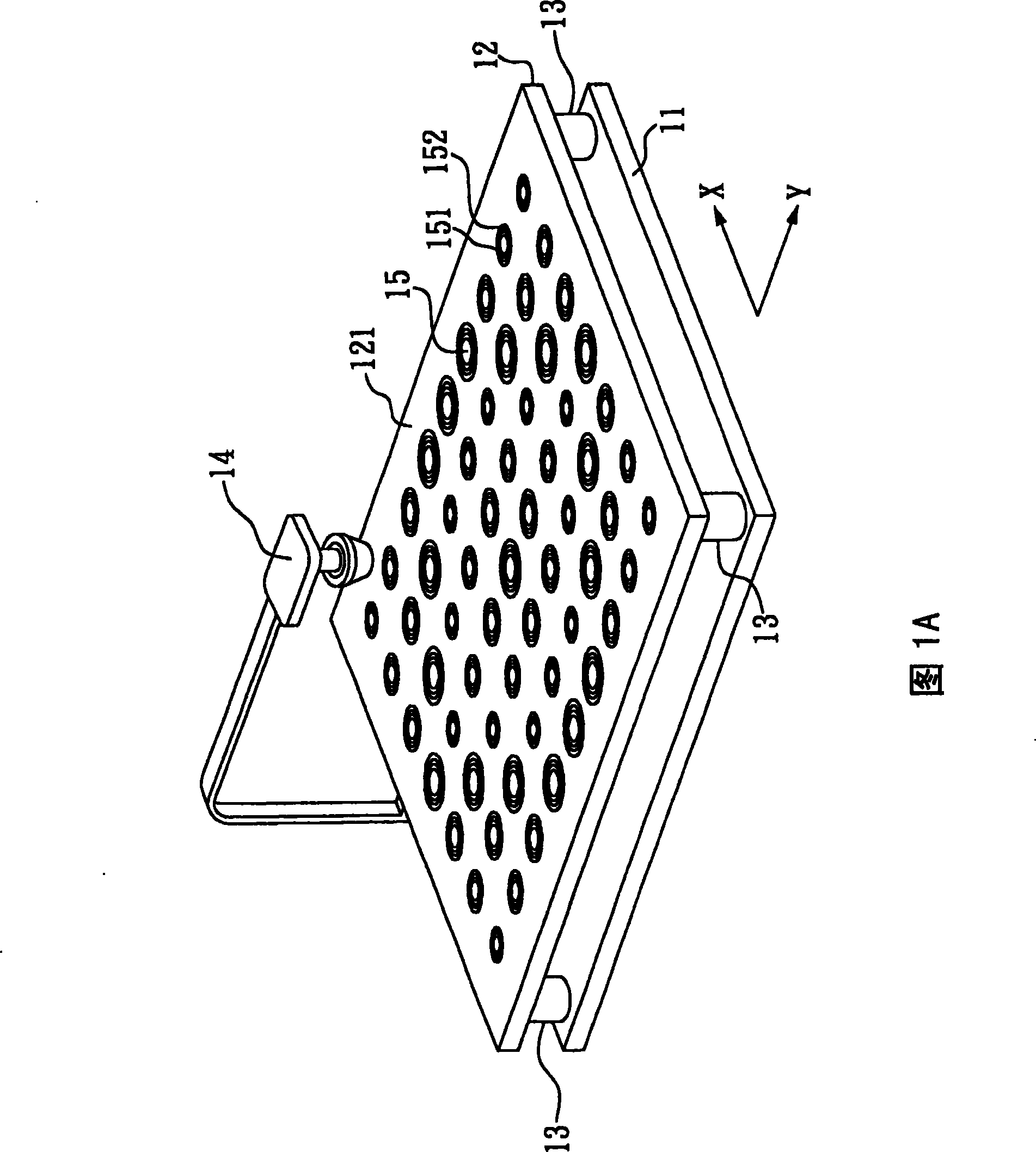
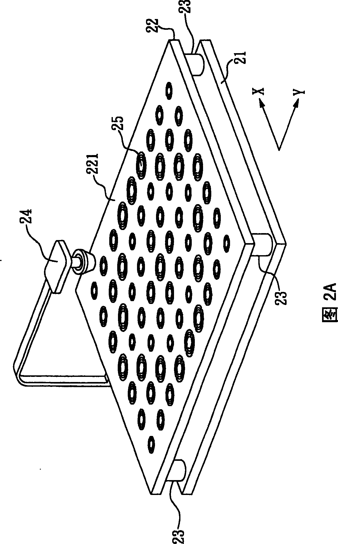
[0033] Figure 2AIt is a schematic diagram of the microstrip reflective array antenna of the first preferred embodiment of the present invention, wherein the microstrip reflective array antenna of the present invention includes a ground plate 21 , a reflective plate 22 , four supporting units 23 and a horn antenna 24 . Wherein, the reflecting plate 22 is supported by four supporting units 23 made of insulating material to keep a certain distance from the grounding plate 21 made of copper plate. In the microstrip reflective array antenna in the first preferred embodiment of the present invention, the distance between the reflective plate 22 and the ground plate 21 is about 6mm. However, in different application occasions, the reflecting plate 22 can also maintain a different distance from the grounding plate 21 by adjusting the lengths of the four supporting units 23 . In addition, the microstrip reflective array antenna in the first preferred embodiment of the present inventi...


PUM


Abstract

The present invention relates to a micro strip reflecting array antenna, in particular to a micro strip array antenna with low across polarized level, which comprises: a grounding plate; a reflecting plate having an upper surface which is distributed with a plurality of micro strip antenna units, and each micro strip antenna unit is provided with an inner ring and an outer ring; a plurality of supporting units for making the reflecting plate positioned above the grounding plate, and a signal emitting unit which is positioned above the reflecting plate. Wherein, the outer ring size of each micro strip antenna unit is determined according the position of the outer ring on the upper surface of the reflecting plate; the outer ring diameter of each micro strip antenna unit has a certain rationrelation with the inner ring diameter of the micro strip antenna unit; and the outer ring and the inner ring are both provided with at least a groove.

Description

technical field [0001] The present invention relates to a microstrip reflective array antenna, especially a microstrip reflective array antenna with low cross polarization level (XPL), which is applied in the field of satellite communication. Background technique [0002] In currently used satellite communication systems (such as satellite TV), due to atmospheric absorption or other reasons, the frequency range that can actually be used for signal transmission is quite limited. However, as the number of signal channels to be transmitted increases significantly (such as hundreds of cable TV channels), the traditional method of using different frequencies to transmit different channels (frequency multitasking) is not enough to cope with this situation. For this reason, in addition to the frequency multitasking method, the industry has used a method of using several signals (with the same frequency) with different polarization directions to respectively transmit program content...

Claims


Application Information

Patent Timeline
Patent Type & Authority Patents(China)
IPC IPC(8): H01Q13/00H01Q21/00H01Q19/10
Inventor 张知难朱俊松
Owner TATUNG COMPANY
Why Eureka
Try Eureka