Electrical source input overvoltage protection circuit

A technology of overvoltage protection circuit and power input, which is applied in the direction of emergency protection circuit device, emergency protection circuit device, circuit device, etc. for limiting overcurrent/overvoltage, and can solve the problem of complex circuit, narrow application range, varistor Or damage to the voltage regulator tube and other problems, to achieve the effect of high response speed, high versatility, and simple circuit

Active Publication Date: 2008-02-06
NUBIA TECHNOLOGY CO LTD
View PDF0 Cites 18 Cited by
  • Summary
  • Abstract
  • Description
  • Claims
  • Application Information

AI Technical Summary

Problems solved by technology

[0004] 1. Add PTC (Positive Temperature Coefficient) thermistor and piezoresistor or voltage regulator tube at the input end of the power supply, which has the advantages of low cost and simple circuit; the disadvantage is that when the input overvoltage time is long The sensitive resistor or voltage regulator tube will be damaged due to severe heat, and its output voltage will rise with the rise of the input voltage, that is, the output voltage is uncertain
[0005] 2. Adding a dedicated OVP chip at the power input terminal has the advantages of small size and relatively simple circuit; the disadvanta

Method used


Image

  • Electrical source input overvoltage protection circuit

Examples


Embodiment Construction

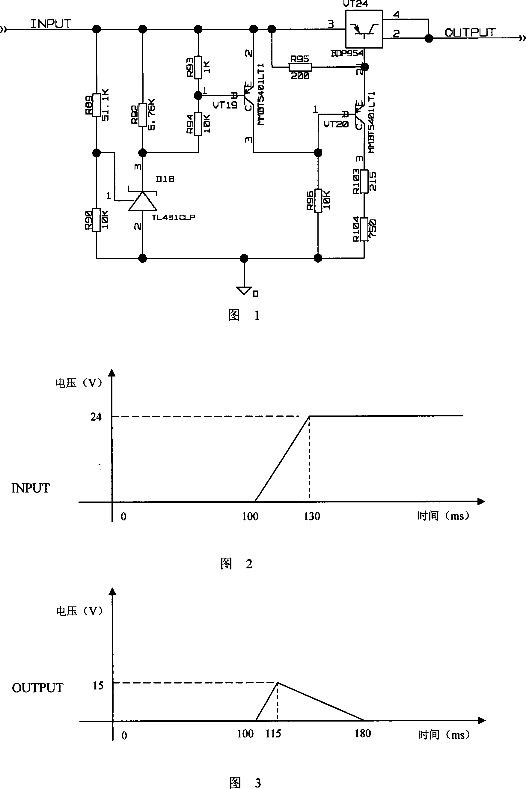
[0019] The present invention will be further described below in conjunction with the accompanying drawings.

[0020] A power supply input overvoltage protection circuit, comprising an overvoltage comparator and a Darlington tube controlled by the overvoltage comparator, the input ends of the overvoltage comparator and the Darlington tube are respectively connected to the overvoltage protection circuit The input terminal of the Darlington tube is connected, the output terminal of the Darlington tube is connected to the output terminal of the overvoltage protection circuit, and the overvoltage comparator controls the on-off of the Darlington tube; if the power supply input voltage is higher than the If the preset overvoltage value of the overvoltage protection circuit is set, the Darlington tube is turned off, and the overvoltage protection circuit is turned off; otherwise, the Darlington tube is turned on, and the input voltage of the power supply passes through the Darlington t...


PUM


Abstract

The present invention discloses a power source input overvoltage protection circuit, which comprises an overvoltage comparator and a Darlington transistor controlled by the overvoltage comoparator. The input ends of the overvoltage and the Darlingto transistor are respectively connected with the input ends of the overvoltage protection circuit, therefore the output end of the Darlington transistor is connected with the output end of the overvoltage protection circuit; the overvoltage comparator controls the on and off of the Darlington transistor; upon the power source input voltage surpassesthe preset overvoltage value of the overvoltage protection circuit, the Darlington transistor is off, and the overvoltage protection circuit is cut off; otherwise the Darlington transistor is on, thepower source input voltage goes through the Darlington transistor and then is output from the output end. The technical plan regarding the present invention adopts pure hardware circuit to realize with simple circuit and at low costs, has commonality, much higher reliability and swift response.

Description

technical field [0001] The invention relates to an overvoltage protection circuit, in particular to a power supply input overvoltage protection circuit. Background technique [0002] Electronic equipment cannot work without a stable power supply. However, in actual use, the input power supply may be abnormal due to various abnormal factors; in addition, it often happens that users use non-standard power supplies, so that the input power supply voltage of the equipment cannot be guaranteed. Once these situations occur, serious consequences are often caused, ranging from the burning of the entire equipment or damage to the input power supply, to causing fires, explosions and other safety accidents. Therefore, it is very important to add a suitable OVP (Over Voltage Protection, overvoltage protection) circuit to the power input terminal of the device. [0003] At present, the commonly used OVP circuits mainly include the following types: [0004] 1. Add PTC (Positive Tempera...

Claims


Application Information

Patent Timeline
IPC IPC(8): H02H9/04
Inventor 廖春生
Owner NUBIA TECHNOLOGY CO LTD
Why Eureka
Try Eureka