Anti-vibration structure for motor

A motor and anti-vibration technology, applied in the direction of electromechanical devices, electrical components, liquid fuel engines, etc., can solve problems such as internal electronic component contact fatigue and aging, electronic system resonance effect and noise, shorten the service life of electronic systems, etc., to maintain Normal function and service life, the effect of avoiding resonance effect and vibration noise

Inactive Publication Date: 2008-02-06
SUNONWEALTH ELECTRIC MACHINE IND
View PDF0 Cites 2 Cited by
  • Summary
  • Abstract
  • Description
  • Claims
  • Application Information

AI Technical Summary

Problems solved by technology

[0006] However, the conventional spindle motor structure mentioned above is likely to cause resonance effect and noise in the electronic system
[0007] This is because the above-mentioned conventional structure, the metal tube 20 and the bottom plate 10 are directly riveted and fixed as a whole through the riveting part 21, so when the spindle motor is running, the vibration generated by the rotation of the rotor 40 and the friction between the rotating shaft 41 and the bearing 22 The generated vibration will be directly transmitted through the bottom plate 10 and affect the performance of the entire electronic system, causing serious resonance effects and vibration noise in the electronic system, especially for optical read-write electronic systems that require high precision. The effect is easy to cause misjudgment of optical reading and writing values, and the electronic system is in a vibration environment for a long time, which is more likely to accelerate the fatigue and aging of the contacts of its internal electronic components and shorten the service life of the electronic system

Method used


Image

  • Anti-vibration structure for motor
  • Anti-vibration structure for motor
  • Anti-vibration structure for motor

Examples


Embodiment Construction

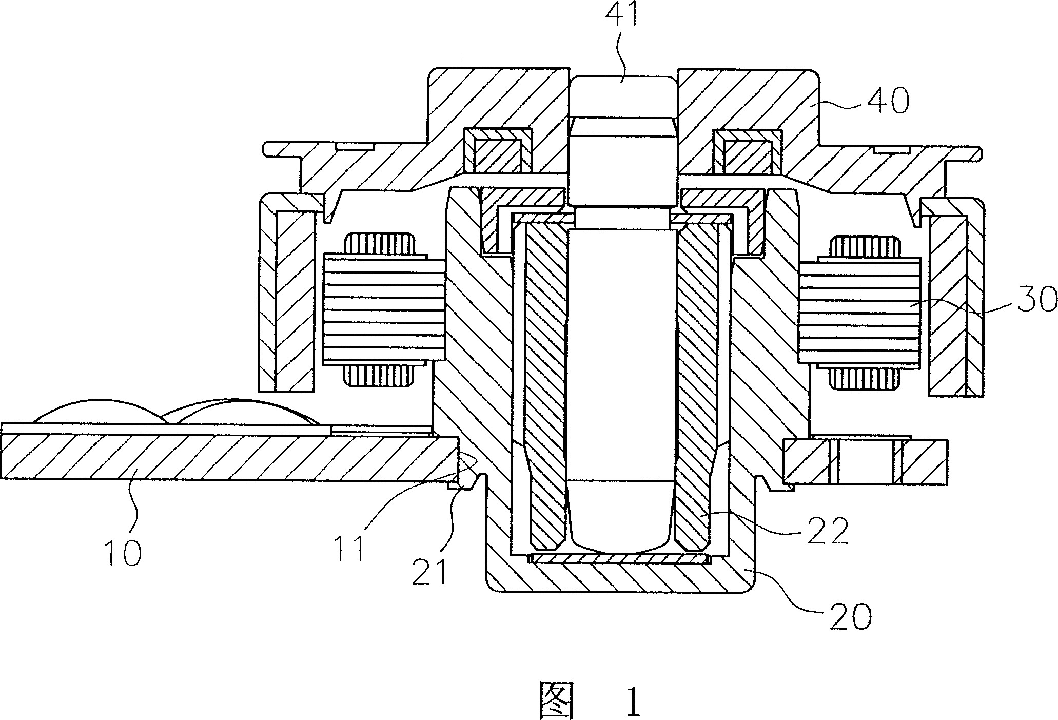
[0023] The invention relates to a vibration-proof structure of a motor. An anti-vibration component with vibration-absorbing and buffering functions is arranged between the metal tube and the bottom plate of the motor, so that the vibration generated by the rotation of the motor rotor and the vibration generated by the friction between the rotating shaft and the bearing are not large. It will be directly transmitted to the bottom plate to block the impact of vibration on the electronic system.

[0024] The following lists the embodiments of the present invention that are actually applied to the spindle motor and describes the structural features and functions of the present invention in detail with reference to the accompanying drawings.

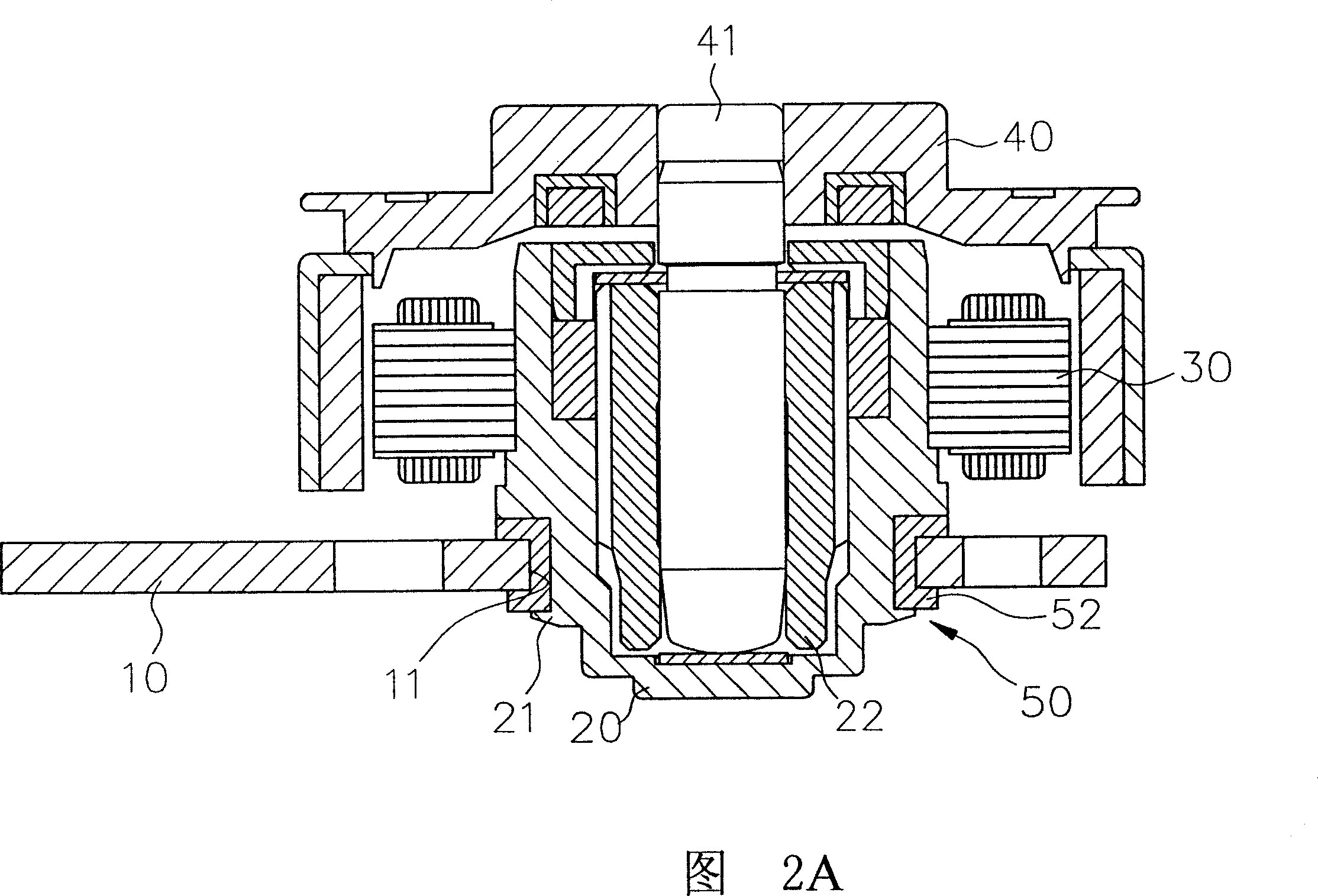
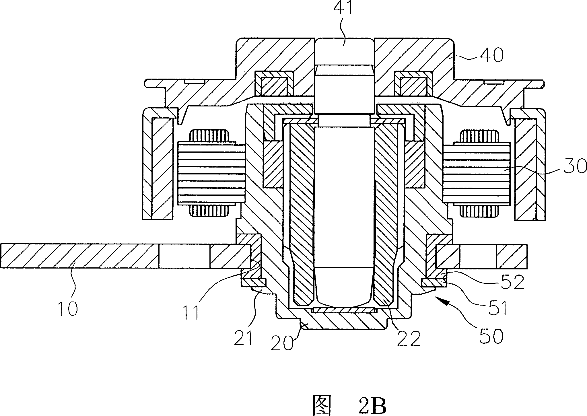
[0025] As shown in FIG. 2A and FIG. 2B , it is the first embodiment of the present invention applied to a spindle motor. The spindle motor includes a bottom plate 10 , a metal tube 20 , a stator assembly 30 and a rotor 40 .

[0026] The bott...


PUM


Abstract

The present invention relates to a motor shocking prevention structure. Motor contains a base plate which has a fixing hole, a metal tube is arranged in the fixing hole, the periphery of the axis tube has a stator group and the inner part of the axis tube is placed with at least one axis, the axis supports to the rotating axis and rotates at the center, and the top of the rotating axis is fixedly connected with the rotator; wherein a shocking prevention assembly is arranged between the metal tube and the fixing hole at the base plate, and the shocking prevention assembly must be made of the flexible material which has the functions of shocking absorbing and amortizing the shocking. Because the shocking prevention assembly is made of the flexible material with the functions of shocking absorbing and amortizing the shocking, therefore the shocking which is generated from the rotator rotating can not directly send to the base plate and the electronic system because of the reviving function of the shocking prevention assembly, which can avoid the electronic system to generate the resonance effect and the shocking noise.

Description

technical field [0001] The invention relates to a vibration-proof structure for a motor, in particular to a practical structure that can block and buffer the vibration of the motor from being transmitted to the electronic system, so as to protect the electronic system and maintain its normal function and service life. Background technique [0002] The spindle motor is used inside the electronic system as the main source of driving power. As shown in FIG. 1 , the spindle motor mainly includes a base plate 10 , a metal tube 20 , a stator assembly 30 and a rotor 40 . [0003] Among them, the bottom plate 10 is the basic structure connecting the spindle motor and the electronic system. Its surface is laid with a PCB and provided with a fixing hole 11. The fixing hole 11 can be inserted into a metal tube 20, and the riveting method of the riveting part 21 will be The metal pipe 20 is fixedly combined with the bottom plate 10. The aforementioned riveting method is a known techniqu...

Claims


Application Information

Patent Timeline
Patent Type & Authority Applications(China)
IPC IPC(8): H02K5/24F04D29/66
Inventor 洪银树倪薪富陈国祥
Owner SUNONWEALTH ELECTRIC MACHINE IND
Why Eureka
Try Eureka