Western water closet equipment

A toilet, Western-style technology, applied in construction, water supply installations, flushing toilets, etc.

Inactive Publication Date: 2008-02-06
LIXIL CORP
View PDF1 Cites 2 Cited by
  • Summary
  • Abstract
  • Description
  • Claims
  • Application Information

AI Technical Summary

Problems solved by technology

[0003] In the above-mentioned Japanese Patent Laid-Open No. 10-96255, the air sucked from the drainage flow path downstream of the first trap by the aspirator flows out to the periphery together with the toilet cleaning water, so there is odor or sewage droplets to the urinal. outflow disadvantages

Method used


Image

  • Western water closet equipment
  • Western water closet equipment

Examples


Embodiment Construction

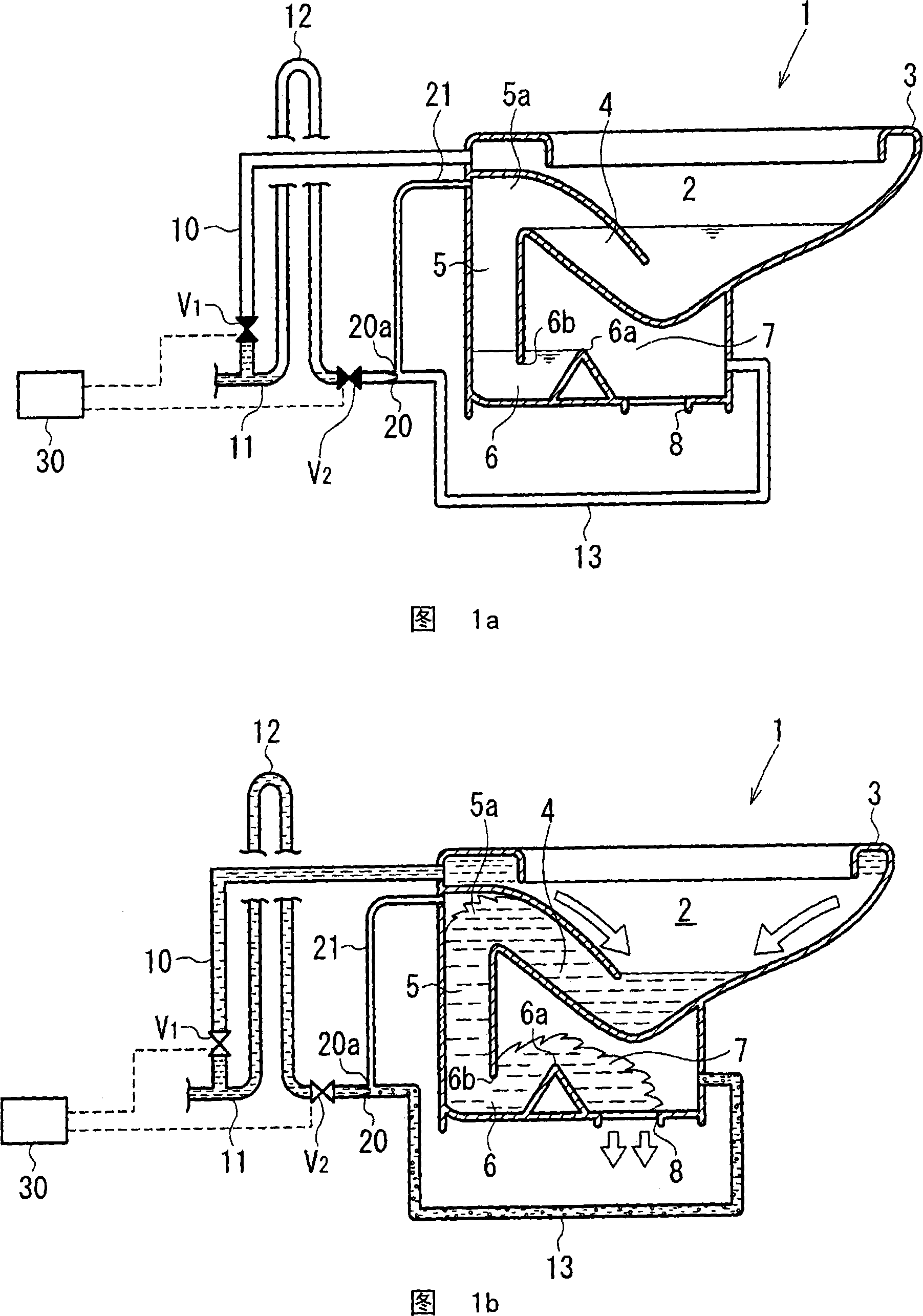
[0011] In the western-style toilet equipment according to the first aspect, the aspirator is arranged to suck out the gas of the drainage flow path connecting the first water trap and the second water trap, and make it flow toward the second water trap together with the discharge water flow of the aspirator. 2 Outflow from the trap or its downstream side. In this way, by sucking the gas in the drainage channel, the siphon effect can be generated early. In addition, it is hygienic because the bad smell and sewage droplets in the drainage channel are discharged to the part after the second trap.

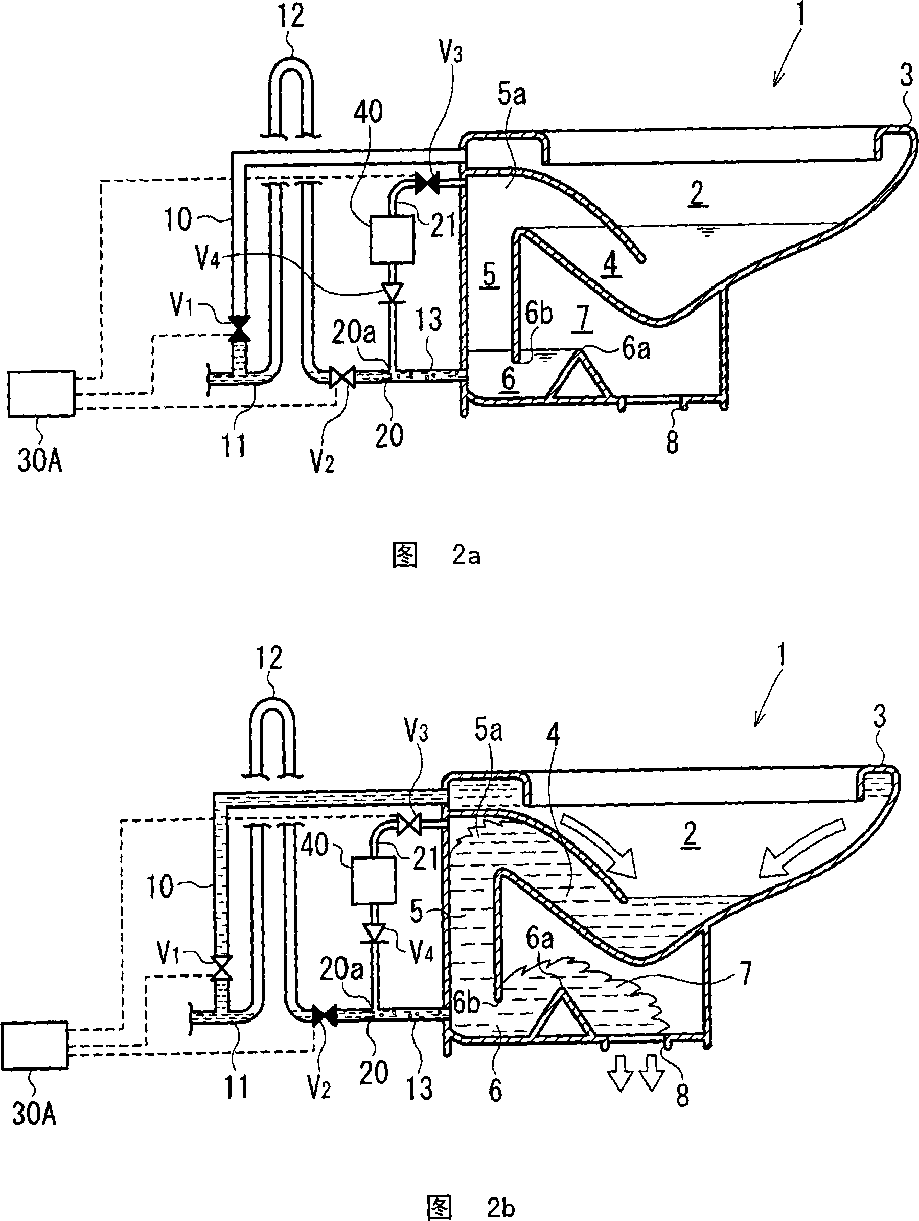
[0012] The western-style toilet device according to the first aspect may include a water supply control device for supplying water to the periphery and the aspirator when cleaning the toilet.

[0013] By arbitrarily controlling the timing of water supply to the periphery and the aspirator by the water supply control device, the toilet can be cleaned early and efficiently.

[0014] Th...


PUM


Abstract

A water supply pipe (10) with a flush control valve V1 is connected to a rim (3) of a toilet body (1) of a hygienic western-style toilet facility that has an ejector for sucking and discharging air from and to a water discharge channel and in which odor and soil water are not supplied to a toilet bowl at the time of flushing. A branch pipe (11) is branched from that part of the water supply pipe (10) which is on the upstream side of the cleaning control valve V1, and the branch pipe (11) is connected to the ejector (20) through a U-shape tube (12) and an ejector water supply valve V2. The water discharge opening of the ejector (20) is connected to a second water discharge channel (7) through piping (13). An air suction opening (20a) provided at a throat section of the ejector (20) is connected to one end of a negative pressure transmission channel (21). The other end of the negative pressure transmission channel (21) is connected to the upper end (5a) of a rising section of a first water discharge channel (5).

Description

technical field [0001] The present invention relates to a western-style toilet device having a first water trap and a second water trap, and particularly relates to a western-style toilet device in which a siphon discharge flow is formed earlier by exhausting air from a drainage flow path downstream of the first water trap when cleaning the toilet. Toilet equipment. Background technique [0002] Japanese Patent Application Laid-Open No. 10-96255 discloses a western-style toilet device, which is provided with: a first water trap connected to the lower part of the urinal, the first water trap, and the downstream side of the first water trap. The second trap part of the toilet, the aspirator used to generate negative pressure from the air between the first trap part and the second trap part to form a siphon earlier when the toilet is cleaned. [0003] In the above-mentioned Japanese Patent Laid-Open No. 10-96255, the air sucked from the drainage flow path downstream of the fir...

Claims


Application Information

Patent Timeline
Patent Type & Authority Applications(China)
IPC IPC(8): E03D11/02
Inventor 白井康裕
Owner LIXIL CORP
Why Eureka
Try Eureka