Safety interlock and protection circuit for permanent magnet motor drive

A permanent magnet motor and electric motor technology, applied in the direction of motor generator control, AC motor control, motor/generator/inverter limiter, etc., can solve the problem of circuit damage and can no longer provide safety door lock/braking mechanism, Failure and other issues

Inactive Publication Date: 2008-02-06
INTERNATIONAL RECTIFIER COEP
View PDF0 Cites 14 Cited by
  • Summary
  • Abstract
  • Description
  • Claims
  • Application Information

AI Technical Summary

Problems solved by technology

Once damage occurs in the electrical system, it may no longer be possible to provide a safety door lock / brake mechanism as any circuitry on the circuit board may also be damaged or fail

Method used


Image

  • Safety interlock and protection circuit for permanent magnet motor drive
  • Safety interlock and protection circuit for permanent magnet motor drive
  • Safety interlock and protection circuit for permanent magnet motor drive

Examples


Embodiment Construction

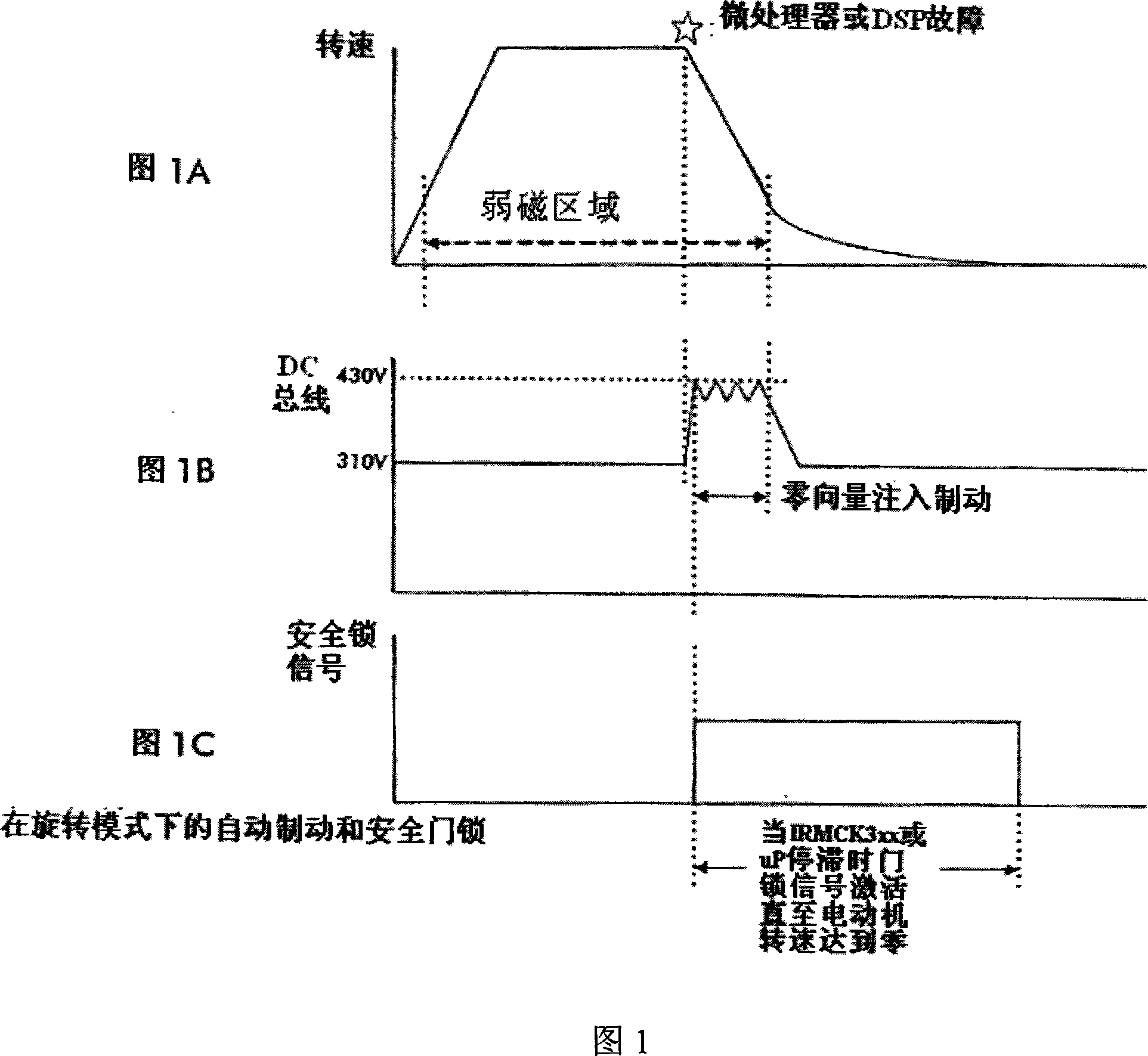
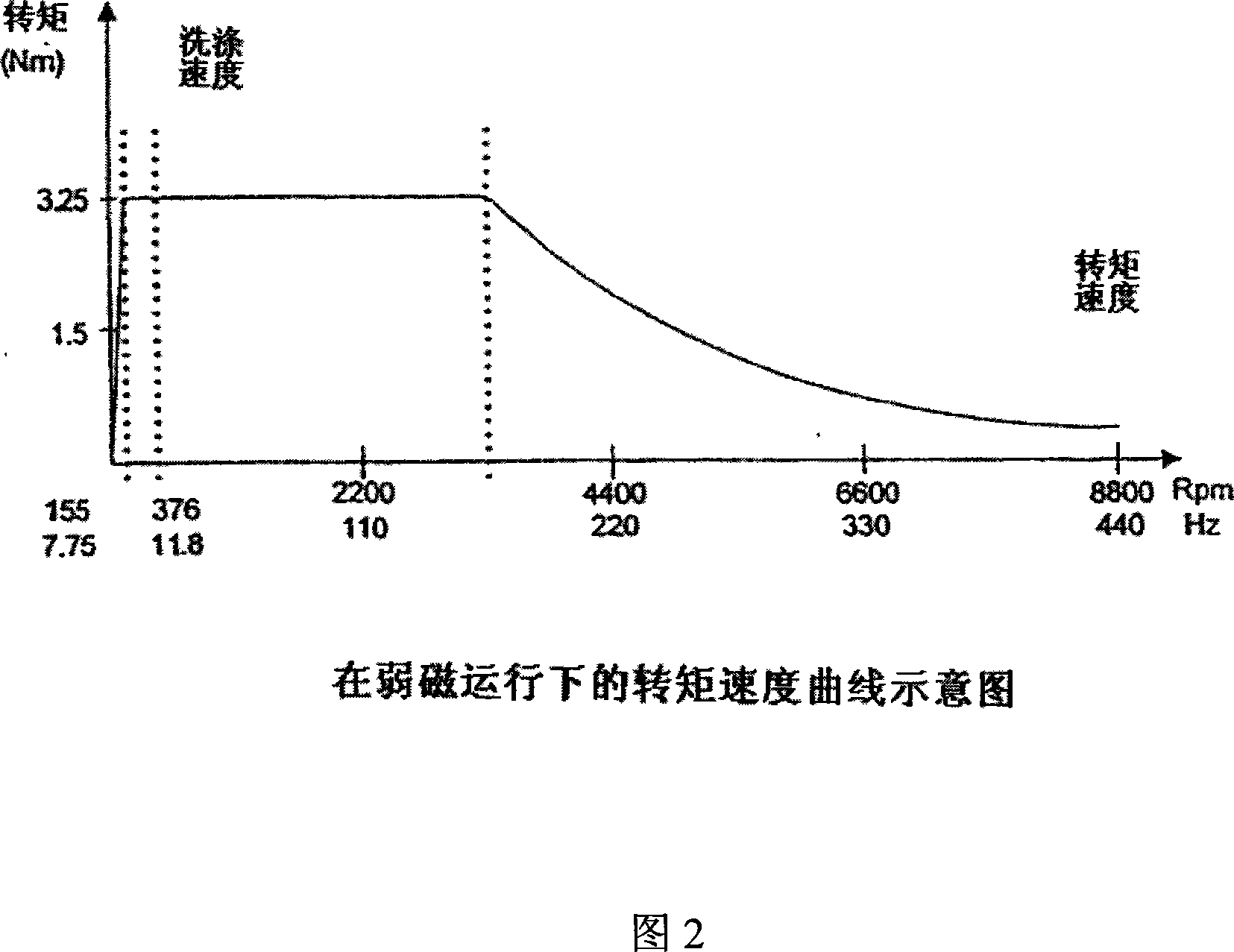
[0021] Referring now to the drawings, Figure 1 shows the state of the most dangerous situation that would occur if the controller were to fail during field weakening operation of the motor in rotation mode. The mode of operation shown is in the high speed rotation mode with deep field weakening of the permanent magnet motor. In the case shown, the controller fails when the last moment of the spin mode is reached, the rotational speed reaches the highest value of the spin mode, and the field weakening is in the deepest region. The failures are shown by the stars in the top plot of Figure 1 (Figure 1A). Figure 2 shows the motor torque speed curve. As shown in Figure 2, the point of failure is near the end of high-speed rotary operation, as shown in the example, close to 8800 revolutions per minute.

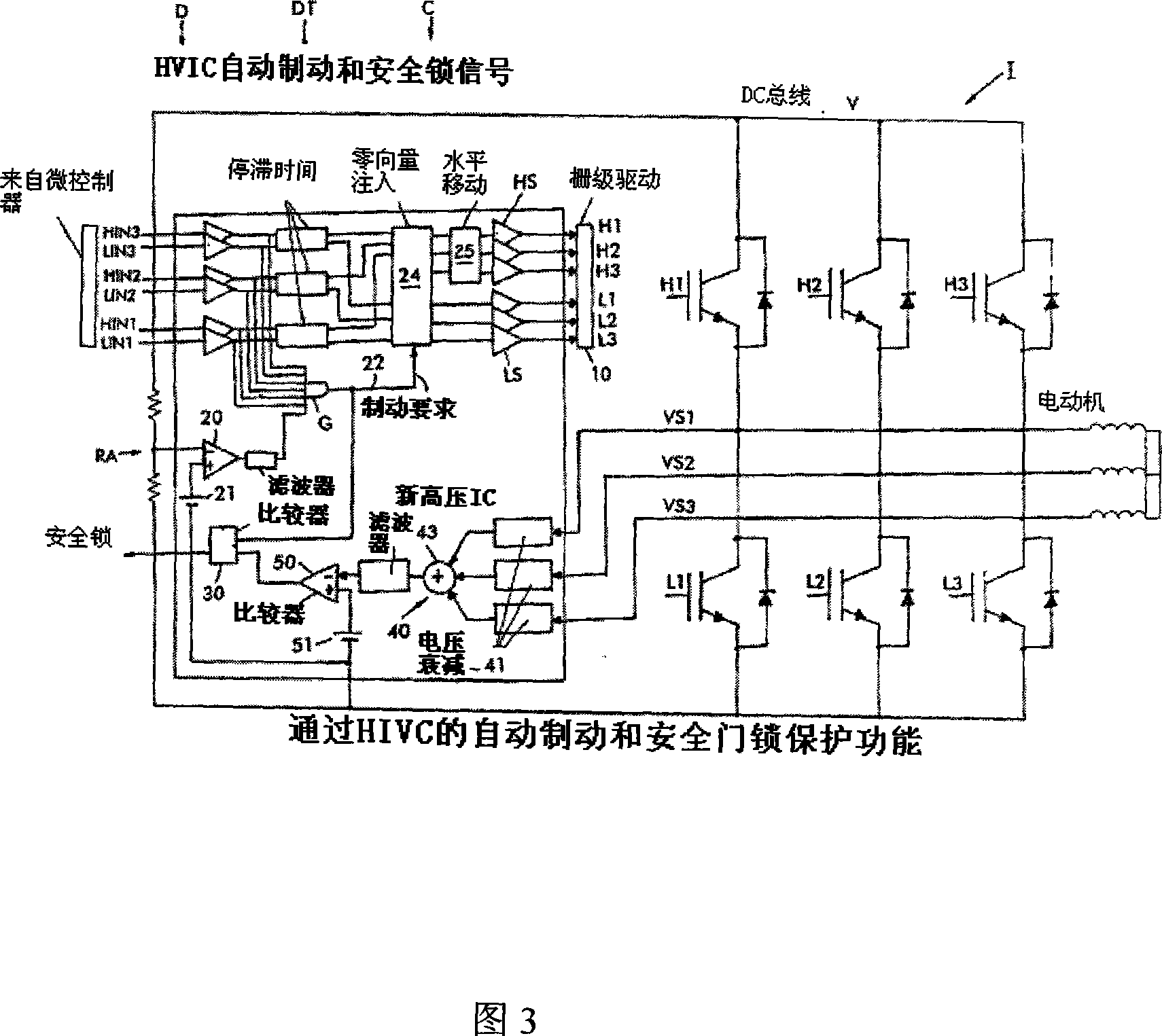
[0022] FIG. 3 shows part of the circuit of a controller C driving a frequency converter I comprising three half-bridges comprising insulated-gate bipolar transistors (IGBTs), as i...


PUM


Abstract

A circuit for protecting against controller failure wherein the controller provides control signals for controlling a DC to AC inverter fed by a DC bus and driving a permanent magnet motor, the circuit comprising a first circuit for monitoring the DC bus voltage and, in the event the DC bus voltage exceeds a first threshold due to a counter EMF generated by the motor, for producing a signal to the controller to provide a switch state to the inverter whereby the counter EMF is dissipated substantially in a motor circuit resistance of the permanent magnet motor as a result of a short circuit condition provided by the switch state of the inverter, thereby preventing the DC bus voltage of the inverter from exceeding the first threshold and causing the permanent magnet motor speed to be reduced.

Description

[0001] related application [0002] This application claims priority and the benefit of US Provisional Application 60 / 652,861, filed February 14, 2005, entitled SAFETY DOOR LOCK ANDPROTECTION CIRCUIT FOR PM MOTOR BASED WASHER APPLICATION, the entire contents of which are hereby incorporated by reference. technical field [0003] The present invention relates to a safety interlock and protection circuit for driving a permanent magnet motor in a DC-AC (direct current-alternating current) frequency converter motor controller, for example, driving the drum of a washing machine. The circuit according to the invention performs the door lock function and provides overvoltage protection and motor braking in the event of a main motor controller failure and loss of control while the permanent magnet motor is still running. Background technique [0004] Permanent magnet motors have higher power density and torque per amp than induction motors. Induction motors were commonly used in wa...

Claims


Application Information

Patent Timeline
Patent Type & Authority Applications(China)
IPC IPC(8): H02P3/00H02M5/40H02P27/00
Inventor G·加利T·塔卡哈希
Owner INTERNATIONAL RECTIFIER COEP
Why Eureka
Try Eureka