

Heat supply system block-proof device
A heat supply system and anti-blocking technology, which is applied to valve devices, cocks including cut-off devices, filtration and separation, etc., can solve the problems of safety hazards, high water temperature in the heating network, etc., and achieve the effect of prolonging the service life and not polluting the environment
Inactive Publication Date: 2008-02-13
TIANJIN JINNAN KAIDA ELECTRONIC CO LTD
View PDF0 Cites 5 Cited by
- Summary
- Abstract
- Description
- Claims
- Application Information
AI Technical Summary
Problems solved by technology
[0002] At present, in order to prevent clogging in the heating system, a filter is installed on the side of the heat meter in the direction of water in advance. When the filter is blocked by impurities, the hot water operation has to be stopped, and the filter is manually dismantled and replaced, which is time-consuming. It costs materials, and the temperature of the water in the heating network is high, so there are potential safety hazards
Method used
View moreImage
Smart ImageViewing Examples

Examples
Embodiment
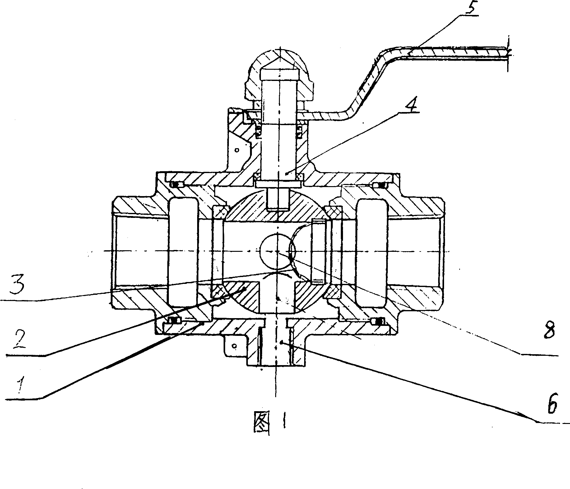
[0007] Embodiment: An anti-blocking device for a heating system, in which a blowdown recoil hole 8 is drilled on the back of the ball-type valve core 2, which directly communicates with the diameter hole of the ball-type valve core, and a temperature hole is drilled on the bottom surface of the ball-type valve core 2. Sensor jack 6, this hole directly communicates with the diameter hole of spheroid type spool, on the diameter hole orifice of spheroid type spool water inlet direction side, the hemispherical strainer 3 that protrudes inward is set.
Login to View More PUM
 Abstract
The invention is an anti-blocking device of a heat supply system. A waste discharging and back washing hole is drilled at the back of a spherical valve core, and communicates directly with a drift diameter hole. A temperature sensor insertion hole is drilled under the spherical valve core, and communicates directly with the drift diameter hole. A hemispherical sieve projecting inwards is arranged at a mouth of the drift diameter hole at the water inlet side of the spherical valve core. The invention is provided with the advantage that the device can discharge sundries quickly without changing a part, the device is safe and causes no pollution to the environment, and the usable life of the device is prolonged.
Description
technical field [0001] The invention relates to an anti-blocking device for a heating system. Background technique [0002] At present, in order to prevent clogging in the heating system, a filter is installed on the side of the heat meter in the direction of water in advance. When the filter is blocked by impurities, the hot water operation has to be stopped, and the filter is manually dismantled and replaced, which is time-consuming. It costs materials again, and the temperature of the water in the heating network is high, so there is a potential safety hazard. Contents of the invention [0003] The object of the present invention is to overcome the above defects and provide an anti-blocking device for a heating system. [0004] The technical solution of the present invention is: an anti-blocking device for a heating system, which is characterized in that: a blowdown recoil hole communicating with the through hole of the valve core is drilled on the back of the ball-typ...
Claims
Login to View More Application Information
Patent Timeline
 IPC IPC(8): F16K5/06F16K37/00B01D35/04
Inventor崔连凯
OwnerTIANJIN JINNAN KAIDA ELECTRONIC CO LTD