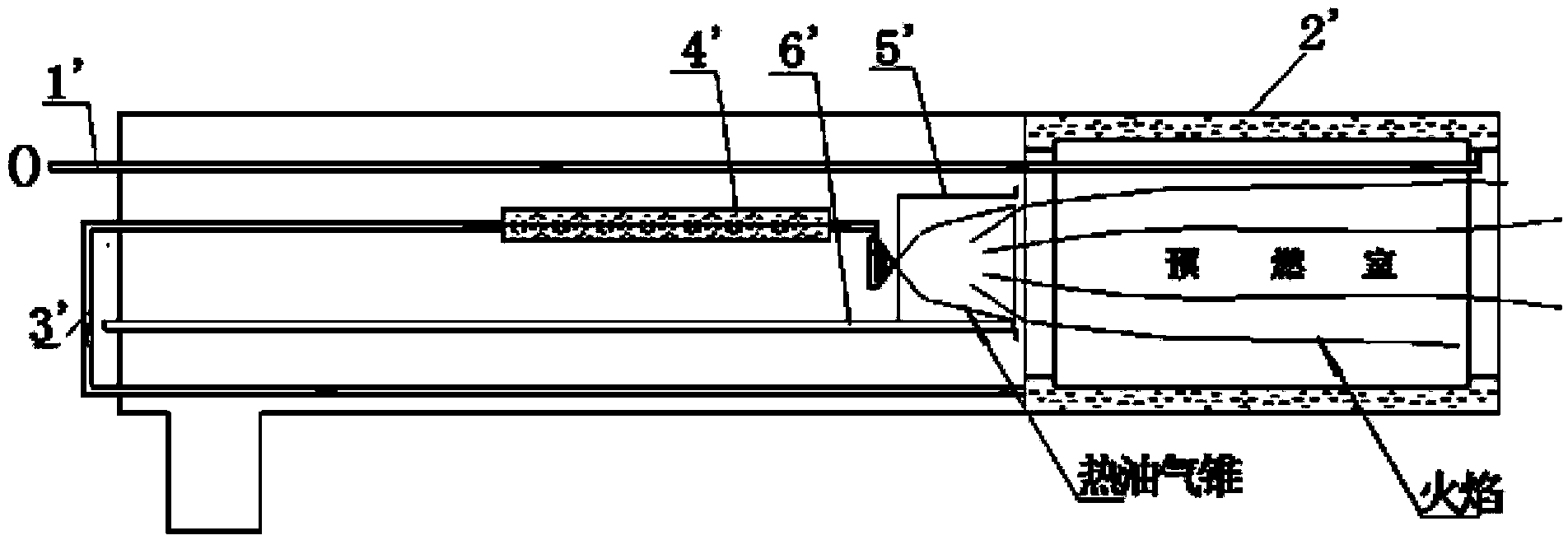
Electric heating mechanical type micro-oil-gasification combustor

A technology of burners and gasifiers, which is applied in the direction of burners, burners burning powder fuel, and combustion methods, etc., can solve the problems of oil dripping, black smoke, etc., achieve no pollution to the environment, high combustion efficiency, and solve Easy to drip oil and black smoke effect

Active Publication Date: 2015-01-14
YANTAI LONGYUAN POWER TECH
View PDF7 Cites 3 Cited by
  • Summary
  • Abstract
  • Description
  • Claims
  • Application Information

AI Technical Summary

Problems solved by technology

[0007] The purpose of the present invention is to propose an electro-thermomechanical micro-oil gasification burner, which has high combustion efficiency in the initial ignition stage, and solves the

Method used


Image

  • Electric heating mechanical type micro-oil-gasification combustor
  • Electric heating mechanical type micro-oil-gasification combustor
  • Electric heating mechanical type micro-oil-gasification combustor

Examples


Example Embodiment

[0042] The technical solution of the present invention will be further described in detail below through the drawings and embodiments.

[0043] Figure 5 Shown is the schematic diagram of the structure of the micro-gasification burner of the present invention; Image 6 Shows Figure 5 Schematic diagram of the working principle. Such as Figure 5 , Image 6 , Figure 14 As shown, the micro-gasification burner provided by the present invention has the same structural parts as the micro-gasification burner in the prior art, including the four-head spiral groove gasifier 1, the air distribution cylinder 2, the burner 3, and the ignition gun. 4. Mechanical atomizing oil gun 5, first oil inlet pipe 6 and second oil inlet pipe 7, of which:

[0044] The right end of the air distribution cylinder 2 is matched with the left end of the four-head spiral groove vaporizer 1. The ignition gun 4 and the mechanical atomizing oil gun 5 are both assembled in the burner 3, and the ignition end of the ...


PUM


Abstract

The invention relates to an electric heating mechanical type micro-oil-gasification combustor. The electric heating mechanical type micro-oil-gasification combustor comprises a four-head spiral groove gasification device, an air distribution barrel, a combustion stabilization device, an ignition gun, a mechanical atomization oil gun, a first oil inlet pipe and a second oil inlet pipe. The mechanical atomization oil gun comprises a gun rod and a rotational flow disc spray nozzle assembly. The gun rod comprises an inlet end and an outlet end. The rotational flow disc spray nozzle assembly is arranged at the outlet end of the gun rod. The mechanical atomization oil gun further comprises a base and a heating element. The base is arranged at the inlet end of the gun rod. The heating element is fixedly connected with the base and is located in an inner cavity of the gun rod. Cold fuel oil sequentially passes through the four-head spiral groove gasification device and the second oil inlet pipe through the first oil inlet pipe, enters an inner cavity of the gun cavity, and is heated through the heating element to form hot oil gas; the hot oil gas enters the rotational flow disc spray nozzle assembly, forms hot oil mist again, and is sprayed out. At the initial ignition stage, the combustion efficiency is high, and the problems that at the low-temperature cold state initial ignition stage, an existing electric heating mechanical type micro-oil-gasification combustor is prone to oil dripping and black smoke emission are solved.

Description

technical field [0001] The invention relates to a pulverized coal burner, in particular to an electrothermomechanical micro-oil gasification burner. Background technique [0002] At present, the ignition technology with small oil gun and less oil has been widely used in boilers, with less equipment investment, high reliability and strong practicability. Micro-oil gasification ignition of pulverized coal technology is the development of small oil gun ignition technology. The combustion temperature of gasification fuel is higher, and the pyrolysis effect on coal powder is improved during ignition, which is more fuel-efficient when igniting coal powder. [0003] For the convenience of description, the "left" and "right" referred to below are consistent with the left and right directions of the drawings themselves. [0004] Electric micro-oil gasification burners mostly use oil guns to ignite, and mechanical atomization oil guns are commonly used. figure 1 Shown is a schematic...

Claims


Application Information

Patent Timeline
IPC IPC(8): F23D1/00F23D11/44F23D11/36
CPCF23D1/00F23D11/36F23D11/448
Inventor 曹琴付玉玲李本伟孙继国蔡巍王秋粉姜志军林涛
Owner YANTAI LONGYUAN POWER TECH
Why Eureka
Try Eureka