
Liquid ejecting apparatus

A liquid and liquid box technology, applied in printing and other directions, can solve problems such as unsuitable operations and achieve the effect of improving workability

Inactive Publication Date: 2008-02-20
SEIKO EPSON CORP
View PDF1 Cites 3 Cited by
  • Summary
  • Abstract
  • Description
  • Claims
  • Application Information

AI Technical Summary

Problems solved by technology

Therefore, when a cartridge holder 100 located in the middle (in the middle) among the plurality of cartridge holders 100 integrated as shown in FIG.
[0012] In the case of taking out one cartridge holder, it is necessary to perform complicated work of taking out all the cartridge holders from the flow path unit assembled with the plurality of cartridge holders and then disassembling each cartridge holder, which is not suitable for work. of

Method used


Image

  • Liquid ejecting apparatus
  • Liquid ejecting apparatus
  • Liquid ejecting apparatus

Examples


Embodiment Construction

[0075] Hereinafter, an embodiment of a liquid ejecting apparatus including a cartridge holder of the present invention will be described with reference to the drawings.

[0076] In addition, in the present embodiment, a case where the liquid ejecting device is applied to a printing machine as a media processing device will be described as an example.

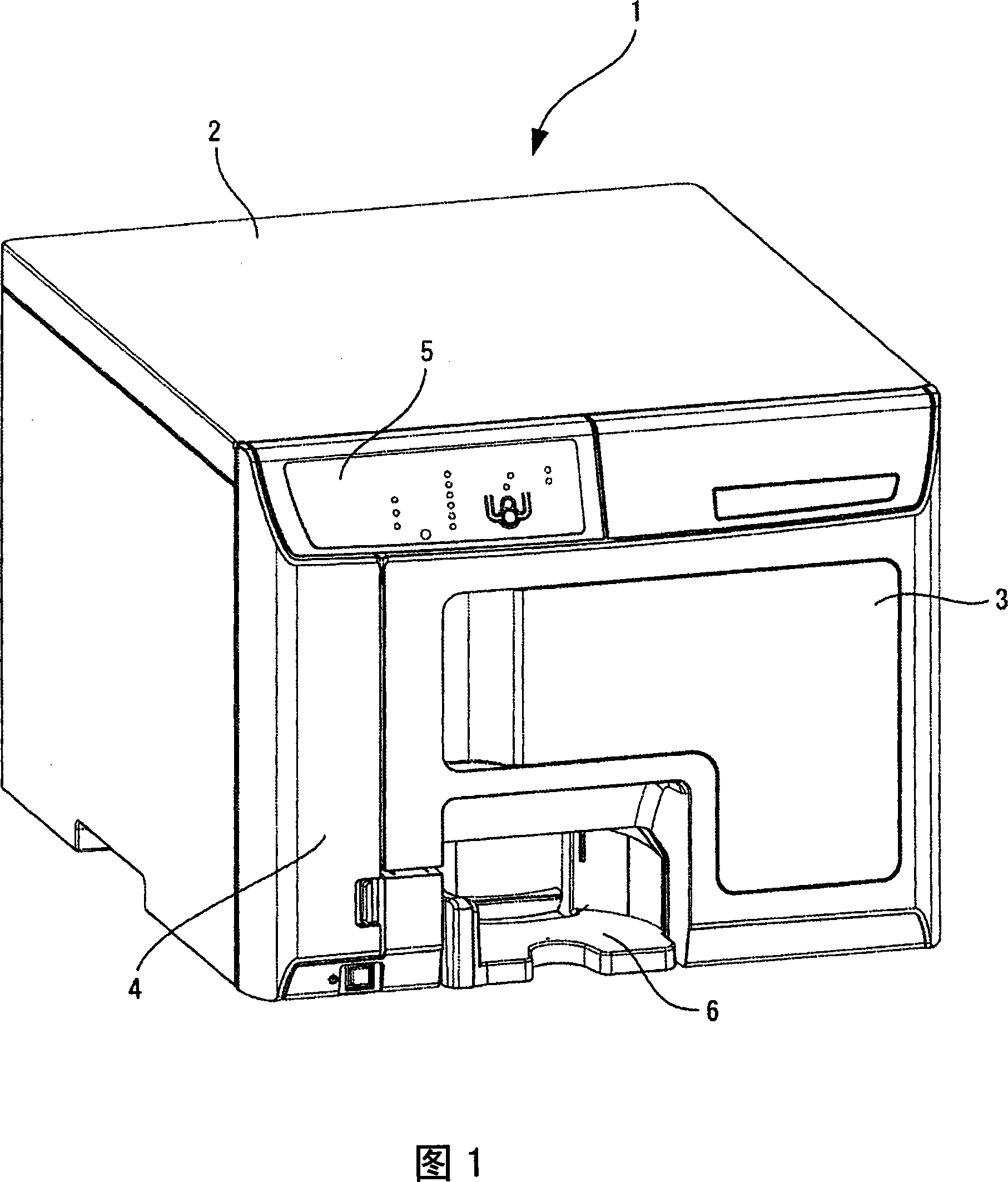
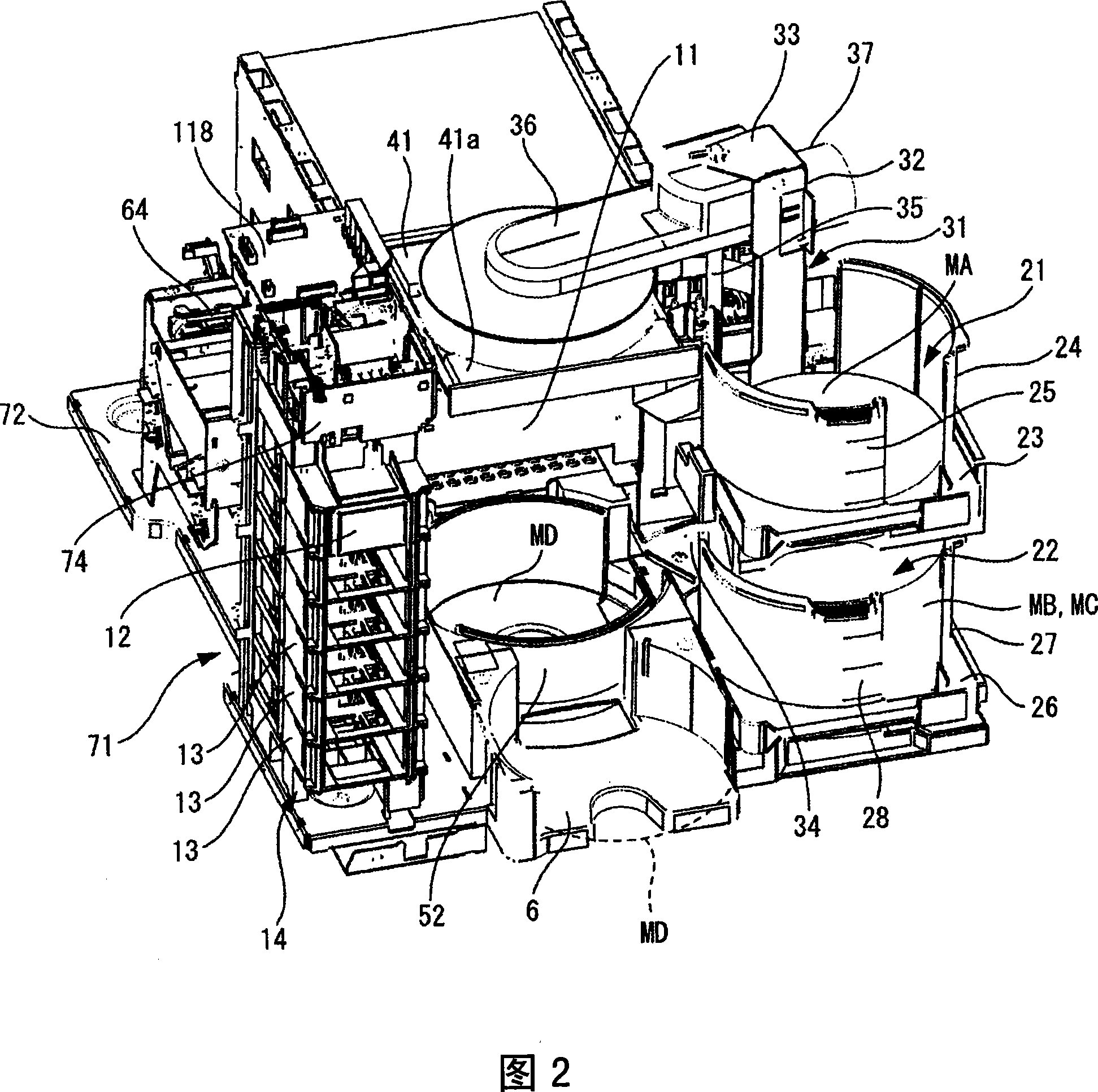
[0077] 1 is an external perspective view of a printing machine (media processing device), FIG. 2 is a front perspective view of the printing machine with its casing removed, FIG. 3 is a rear perspective view of the printing machine with its casing removed, and FIG. 4 FIG. 5 is a perspective view of a portion of the liquid ejection device installed in the printing machine, and FIG. 5 is a schematic diagram of the internal configuration of the printing machine.

[0078] The printing machine 1 is a media processing device that writes data to a disc-shaped medium such as a CD or a DVD, or prints on a label surface of the medium, and...


PUM


Abstract

A liquid ejecting apparatus includes: a flow channel unit, having a liquid flow channel for supplying a liquid stored in a liquid cartridge; and a plurality of cartridge holders, including a first cartridge holder and a second cartridge holder adjacent to each other, and attached to the flow channel unit while the cartridge holders are arranged in a first direction, each of the cartridge holders adapted to hold the liquid cartridge and having a first engaging portion and a second engaging portion. The first engaging portion of the first cartridge holder and the second engaging portion of the second cartridge holder are engageable with each other to lock the first and second cartridge holders, and the first engaging portion of the first cartridge holder and the second engaging portion of the second cartridge holder are disengageable from each other to unlock the first and second cartridge holders when one of the first and second cartridge holders is moved in a second direction that is apart from the flow channel unit.

Description

technical field [0001] The present invention relates to a liquid ejection device having a cartridge holder mounting portion to which a plurality of cartridge holders for holding cartridges containing liquids such as ink are mounted. Background technique [0002] As a representative liquid ejecting device, an ink jet recording device having a recording head for printing by ejecting ink droplets from a nozzle to a recording medium has been widely used. [0003] This recording apparatus includes a carriage and a recording head mounted on the carriage, and prints on the recording medium by ejecting ink from nozzles formed on the recording head while moving the carriage relative to the recording medium. [0004] In such a recording apparatus, it is known to provide a plurality of cartridge carriers in order to accommodate and hold a plurality of ink cartridges containing printing inks (for example, refer to Patent Document 1). [0005] In addition, the ink cartridge accommodates...

Claims


Application Information

Patent Timeline
Patent Type & Authority Applications(China)
IPC IPC(8): B41J2/175
Inventor 萩原宽之丸山昭彦
Owner SEIKO EPSON CORP
Features
  • Generate Ideas
  • Intellectual Property
  • Life Sciences
  • Materials
  • Tech Scout
  • Unparalleled Data Quality
  • Higher Quality Content
  • 60% Fewer Hallucinations
Learn More