
Spinning machine with multi-stage drafting compression unit

A spinning frame and drafting technology, which is applied in the field of ring spinning frames, can solve the problems of unsatisfactory properties of textile yarns

Inactive Publication Date: 2008-02-20
MASCHINENFABRIK RIETER AG
View PDF4 Cites 7 Cited by
  • Summary
  • Abstract
  • Description
  • Claims
  • Application Information

AI Technical Summary

Problems solved by technology

However, the ply properties of the textile yarns produced by this method are not satisfactory

Method used


Image

  • Spinning machine with multi-stage drafting compression unit
  • Spinning machine with multi-stage drafting compression unit
  • Spinning machine with multi-stage drafting compression unit

Examples


Embodiment Construction

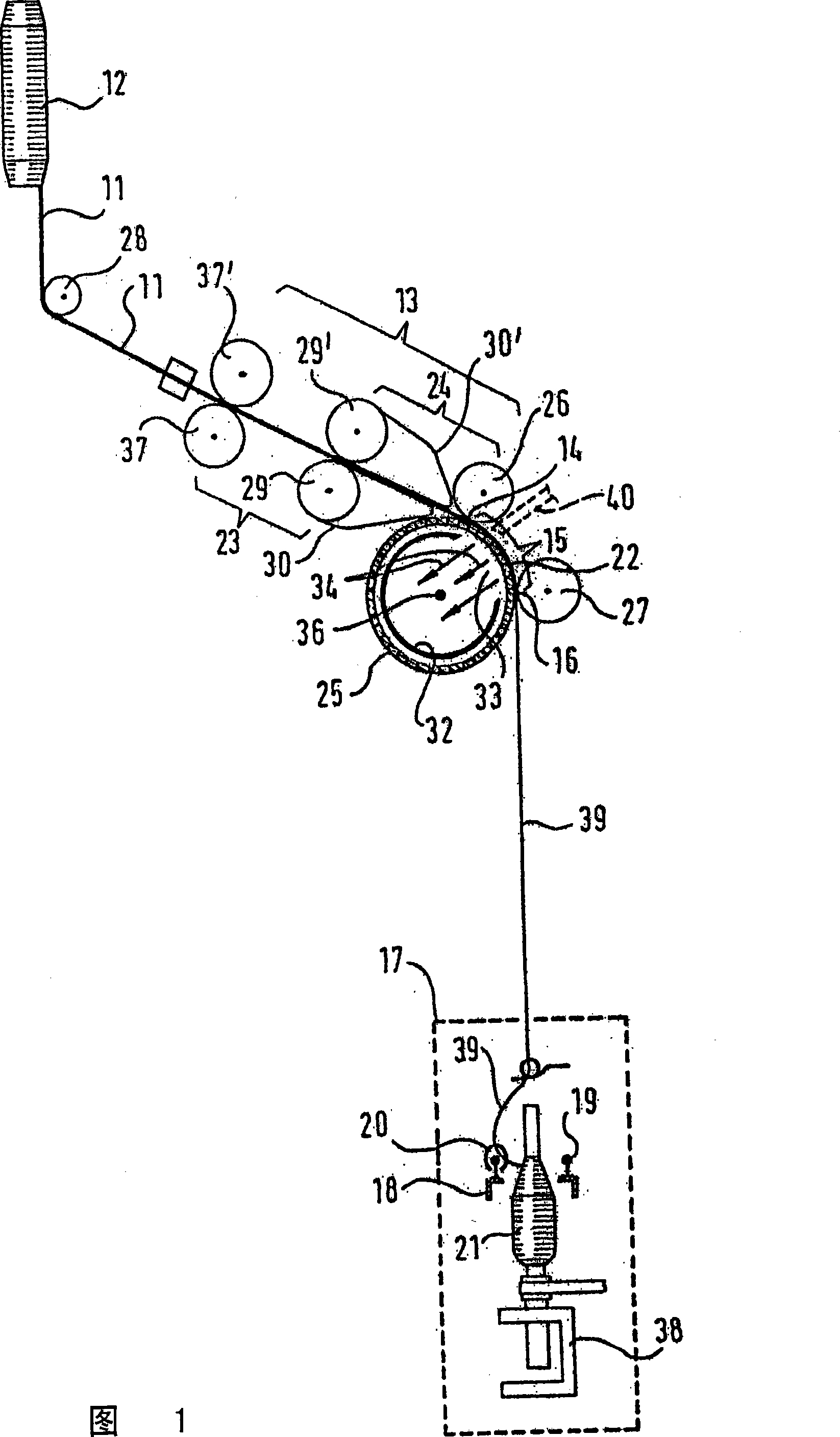
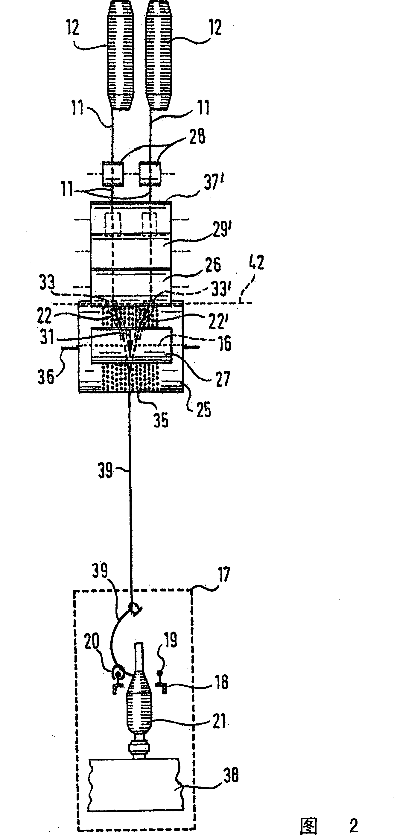
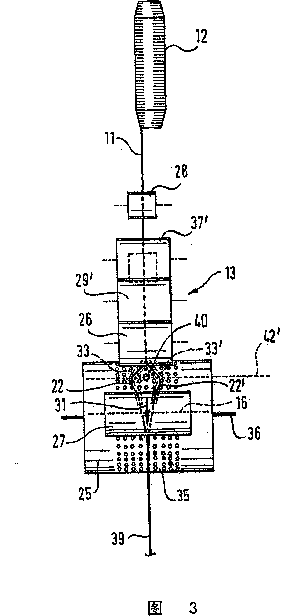
[0022] According to a particular embodiment of the invention, it relates to a spinning frame, in particular a ring spinning frame, which has at least one multistage drafting unit 13 with pairs of rollers 29, and consists of one or two roving bobbins 12 Or one or two bar cans supply fiber bundles, at its pair of outlet rollers 25,26 place or at its pair of outlet rollers 25,26 nears arrange a suction device 25, have the perforated area 35 that spreads over its circumference above, It (suction device), along a path segment 15, on its circumference, moves together with one or more fiber bundles, creating a guiding surface for these fiber bundles, so as to constitute a coagulation stage, in which At least one fibrous web comprising the final draft, but at least not yet substantially twisted or not fully twisted, is coalesced and / or bundled into compact fiber bundles 22, 22' preferably less than 1 mm wide, whereby along The path section 15 moving therewith, directly radially within...


PUM


Abstract

A spinning machine (17) has a drafting unit (13) has a speed control unit (32d) linked to the drafting roller (29) drive (50). The speed of rotation of the individual rollers is not proportional to each other over an extended period of time. The yarn (22) draft varies with time. A ring-spinning machine has a multi-stage drafting section (13) fed by one or two yarn bobbins (12). The assembly has a number of pairs of rollers (29). The first pair of rollers (25, 26) closely co-located with a perforated suction inlet roller (25) extending over a yarn feed section (15). This operates as a gathering stage in which a group of fibres are brought to a width of 1 mm or less. The suction unit consists essentially of a concave perforated pad with converging channels.

Description

[0001] This application is a divisional application of an application whose filing date is 2003.08.07, application number is 03127446.3, and the title of the invention is "spinning frame with multi-stage cohesive drafting unit". technical field [0002] The invention relates to a ring spinning machine, Background technique [0003] With previously known spinning frames of this type (cf. DE 19500036, DE 196 08697), each compact fiber bundle formed on the suction roller is spun into its own single strand after the twisting test gap. In the case of the production of plied yarns, the several strands thus produced are then twisted to form plied yarns. [0004] From EP 0 444 486 A2 it is also known to combine two fiber slivers behind the exit rollers of a drafting unit which contains solid rollers; also known by means of a spindle and essentially freely rotating bell These fibers are processed into textile yarns similar to ply yarns. However, the ply properties of the textile ya...

Claims


Application Information

Patent Timeline
Patent Type & Authority Applications(China)
IPC IPC(8): D01H1/02D01H5/22D01H5/72D01H7/00D01H5/32D01H1/22D01H1/30D01H5/36D01H5/66D01H5/74D01H13/04D02G3/34D02G3/36
CPCD01H5/36D01H5/72D02G3/34D01H5/74D02G3/367
Inventor L·古布泽尔J·温利
Owner MASCHINENFABRIK RIETER AG
Learn More