Power transmission device

A power transmission device and linkage technology, which is applied in the direction of gear lubrication/cooling, can solve the problems of slowing down speed, inability to effectively reduce stirring resistance, inability to obtain sufficient lubrication, etc., and achieve the effect of improving mechanical efficiency

Inactive Publication Date: 2008-02-20
NISSAN MOTOR CO LTD
View PDF1 Cites 5 Cited by
  • Summary
  • Abstract
  • Description
  • Claims
  • Application Information

AI Technical Summary

Problems solved by technology

[0006] First of all, the gear mechanism is set to slow down the oil level drop rate in order to provide sufficient lubrication at low-speed rotations such as when the vehicle is started. However, the lubrication efficiency at low speeds is good. , when rotating at a relatively high speed, it becomes the speed at which the lubrication effect of forced lubrication can be fully obtained. Even if oil pool lubrication is not required, since the oil level can only gradually decrease along a straight line, it may not be able to effectively reduce the stirring resistance
[0007] On the other hand, in order to suppress the increase of agitation resistance accompanying the increase of the rotational speed, the set oil level drop speed is accelerated. At this time, the oil level drops early, and it may not be able to fully obtain the effect of the oil pool type lubrication at low speed rotation. lubrication

Method used


Image

  • Power transmission device
  • Power transmission device
  • Power transmission device

Examples


no. 1 approach

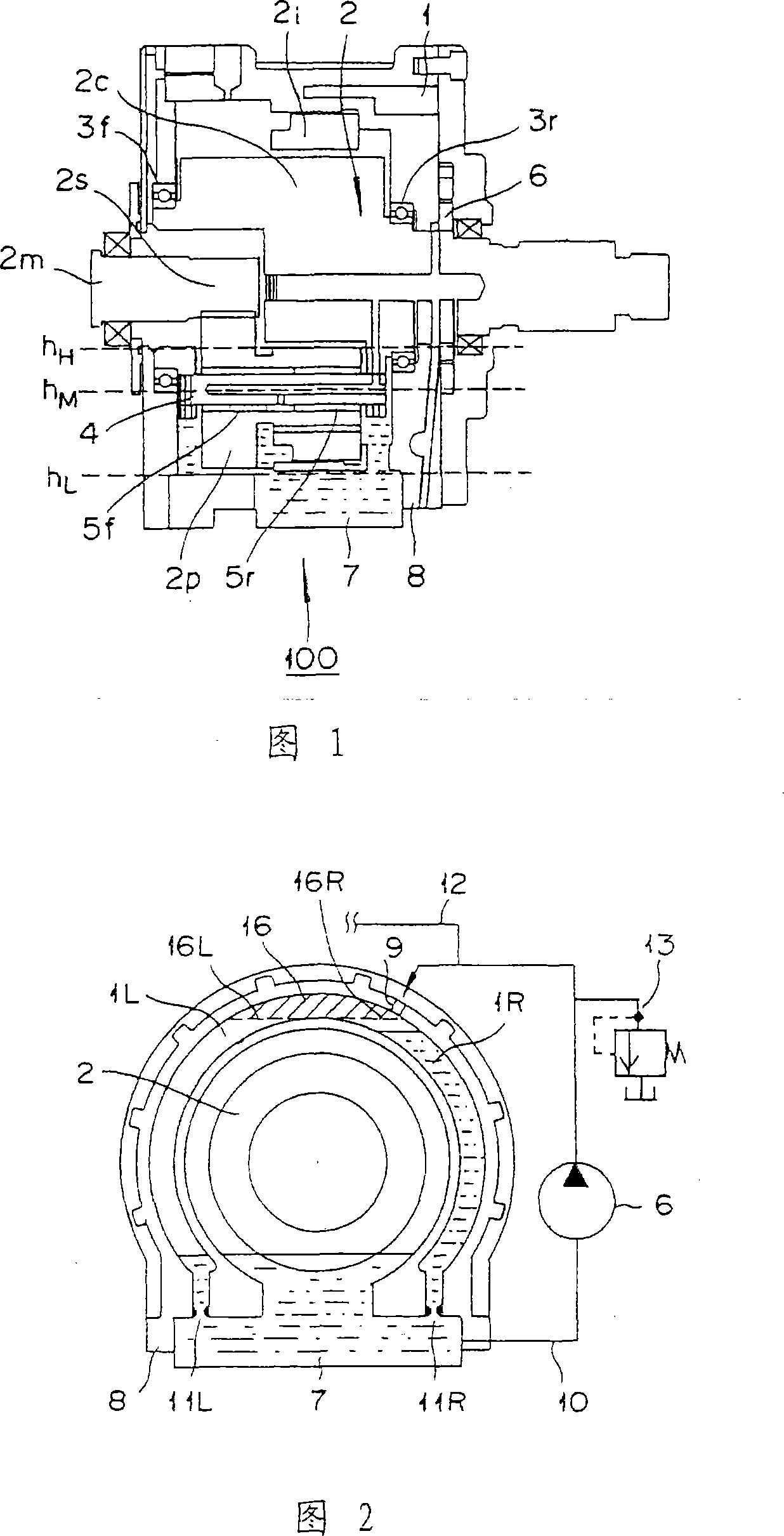
[0051] FIG. 1 is an axial cross-sectional view showing the outline of a power transmission device 100 according to a first embodiment, and FIG. 2 is an axial cross-sectional view of the power transmission device 100 . In addition, in this embodiment, oil has a lubricating effect and a cooling effect.

[0052] First, the outline of the power transmission device 100 of the present embodiment will be described.

[0053] The power transmission device 100 shown in FIG. 1 generally has: a casing 8, which can store oil; a gear mechanism 2, which is accommodated in the casing 8, and is linked with a driving source; an oil pump 6, which is linked with a driving source, and stores oil. The oil in the lower part 7 of the housing 8 is delivered under pressure to lubricate the gear mechanism 2 forcibly; the oil tank 1 stores a part of the oil delivered under pressure from the oil pump 6 .

[0054] The drive source is a motor not shown, and the gear mechanism 2 is connected to a motor shaf...

no. 2 approach

[0095] In the second embodiment, differences from the first embodiment will be described, and overlapping descriptions will be omitted.

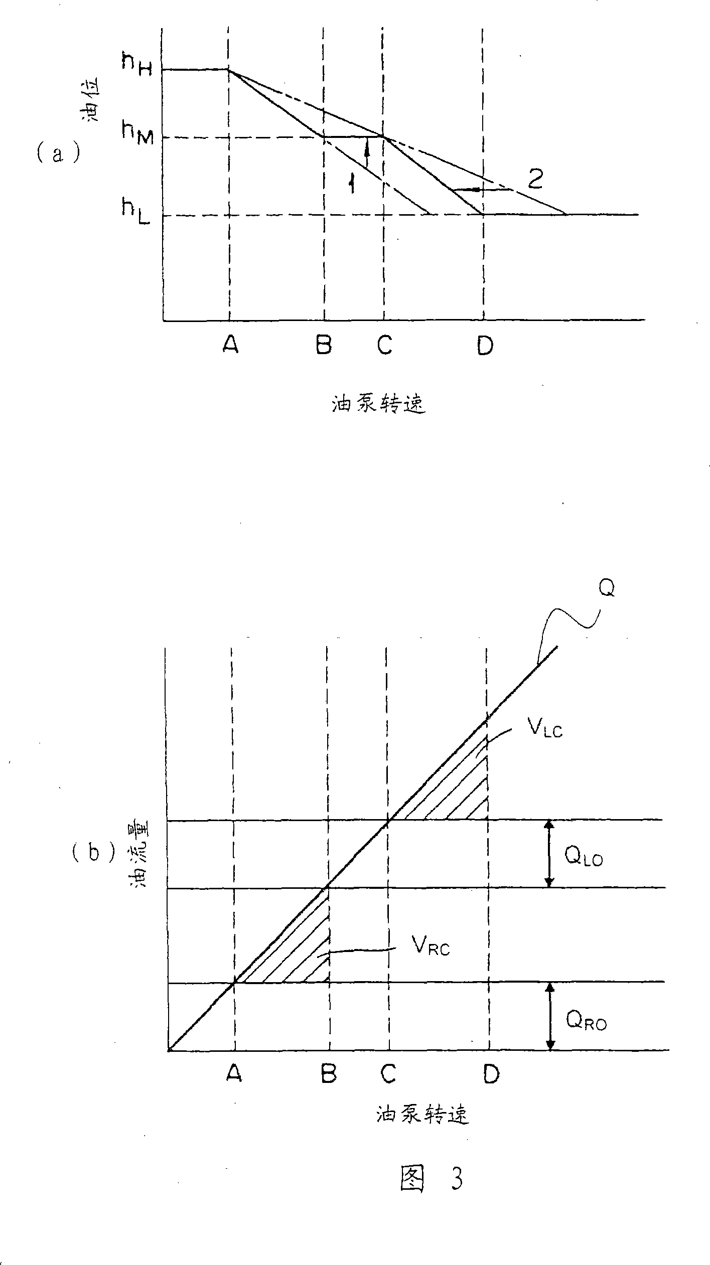
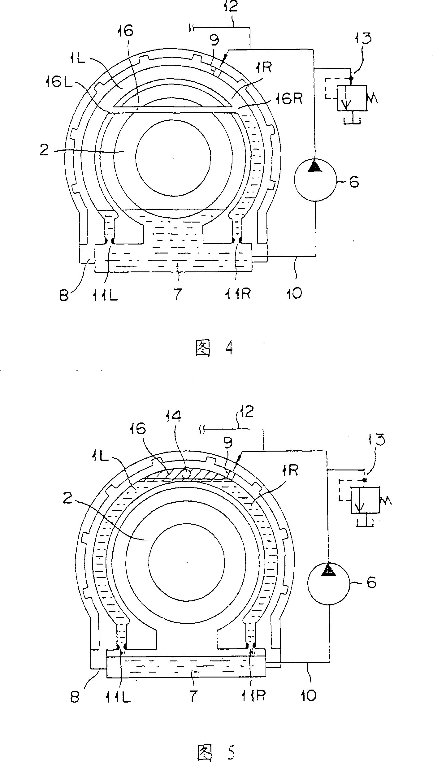
[0096] FIG. 6 is an axially orthogonal cross-sectional view of the lubricating structure of this embodiment, and FIG. 7 is a diagram showing the relationship between the rotational speed of the gear mechanism and the oil level.

[0097] The lubricating structure and lubricating action of this embodiment will be described with reference to FIGS. 6 and 7 .

[0098] 6 shows an example in which the cross-sectional area of ​​the second discharge port 11L at the lower end of the second oil tank 1L is smaller than the cross-sectional area of ​​the first discharge port 11R at the lower end of the first oil tank 1R.

[0099] Thus, the second discharge flow rate Q RO Less than the first discharge flow Q LO , the oil accumulation speed of the second oil tank 1L is faster than the oil accumulation speed of the first oil tank 1R, after the oil pump spe...

no. 3 approach

[0112] In the third embodiment, differences from the first embodiment will be described, and overlapping descriptions will be omitted.

[0113] Fig. 10 is an axially orthogonal sectional view of the power transmission device according to the present embodiment.

[0114] Referring to FIG. 10 , the lubricating structure and lubricating action of this embodiment will be described.

[0115] FIG. 10 shows that in addition to the first discharge port 11R and the second discharge port 11L, a third row communicating with the housing lower part 7 is provided on the tank side wall above the bottom of the first fuel tank 1R and below the communication path 16. Exit 15 implementation. As in the first embodiment, after the supply of oil to the first oil tank 1R is started, if the lubricating oil is filled to the discharge port 15, the oil can also be discharged from the third discharge port 15 to the case lower part 7, and the case lower part can be further The oil level of 7 decreases s...


PUM


Abstract

A power transmission device is provided with a gear mechanism, a case, an oil pump and an oil tank. The gear mechanism is arranged to operate in coordination with a drive source. The case houses the gear mechanism and stores oil for lubricating the gear mechanism. The oil pump is arranged to operate in coordination with the drive source so as to pump the oil stored in the case to lubricate the gear mechanism. The oil tank is arranged to collect a portion of the oil pumped from the oil pump. The oil tank includes a first discharge outlet arranged to discharge the oil collected in the oil tank to the case and a second discharge outlet arranged to discharge collected oil to the case when an amount of the oil collected in the oil tank is equal to or larger than a prescribed amount.

Description

technical field [0001] The invention relates to a power transmission device. Background technique [0002] Generally, in a power transmission device used in a vehicle, a gear mechanism interlocked with a drive source for driving the vehicle, for example, an electric motor, is housed in a casing capable of storing oil (see Patent Document 1). Patent Document 1 discloses a power transmission device capable of improving both lubricating efficiency at low-speed rotation and mechanical efficiency at high-speed rotation. According to this power transmission device, when the vehicle is stopped or running at a low speed, that is, when the gear mechanism interlocked with the drive source is stopped or rotated at a low speed, the amount of oil pressurized and delivered by the mechanical oil pump driven by the gear mechanism is small. Therefore, The oil level in the lower part of the casing is raised, and the lubricating effect is performed by the oil pool type lubrication method, the...

Claims


Application Information

Patent Timeline
Patent Type & Authority Applications(China)
IPC IPC(8): F16H57/04
Inventor 西原隆太
Owner NISSAN MOTOR CO LTD
Why Eureka
Try Eureka