Electrical level output device for guaranting maximum voltage headroom and its method
A technology with the largest margin, applied in measuring devices, adjusting electrical variables, data processing power supplies, etc., can solve the problem of inflexible reference voltage adjustment, achieve large voltage margin, solve inter-symbol interference, and change flexibly.
- Summary
- Abstract
- Description
- Claims
- Application Information
AI Technical Summary
Problems solved by technology
Method used
Image
Examples
Embodiment 1
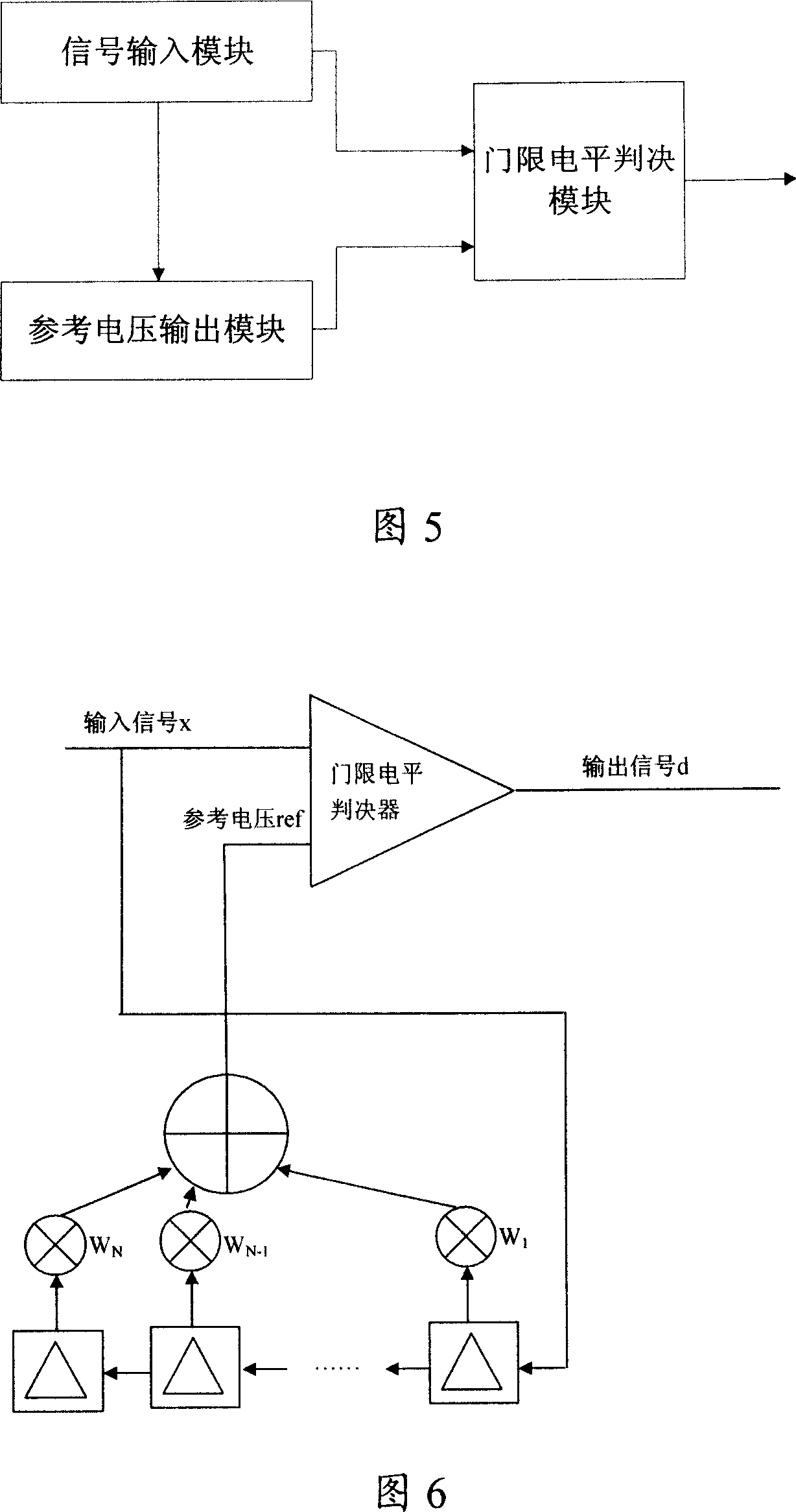
[0078] In this embodiment, a level output device that ensures the maximum voltage margin is proposed, as shown in Figure 5 and Figure 6, including a signal input module, a reference voltage output module and a threshold level judgment module, wherein:
[0079] The signal input module is configured to transmit input signals to the reference voltage output module and the threshold level judgment module;
[0080] The reference voltage output module is configured to output a reference voltage to the threshold level judgment module, and adjust the output value of the next reference voltage according to the current input signal of the signal input module;
[0081] The threshold level judging module is used to determine the current output signal according to the current input signal and the current reference voltage.
[0082] The reference voltage output module in this embodiment is an FIR filter, as shown in FIG. 6, the filter at least includes:
[0083] a shift register group, use...
Embodiment 2
[0095] The principle of this embodiment is the same as that of Embodiment 1, as shown in FIG. 7 , the difference is that this embodiment also includes a coefficient adaptive adjustment module, which is used to receive the input signal currently transmitted by the signal input module, the reference voltage output The reference voltage currently output by the module and the threshold level determine the current output signal of the module, and adjust the coefficients in the coefficient group of the filter according to the three signals.
[0096] In this embodiment, the coefficient adaptive adjustment module includes:
[0097] A sum and difference circuit, configured to obtain an error signal according to the current input signal, the current reference voltage and the current output signal;
[0098] a coefficient calculation unit, configured to calculate and obtain the filter coefficients according to the error signal obtained by the sum and difference circuit;
[0099] A coeffi...
Embodiment 3
[0137] Referring to Figure 5 and Figure 12, the principle of this embodiment is the same as that of Embodiment 1, the difference is that the reference voltage output module in this embodiment is an IIR filter, and the filter at least includes:
[0138] The first differential circuit is used to obtain the difference between the current input signal and the current output reference voltage;
[0139] a shift register group, used to store the difference generated by the first difference making circuit;
[0140] a coefficient group for storing coefficients required for outputting the reference voltage;
[0141] a multiplier for multiplying the difference stored in the set of shift registers with the coefficients in the set of coefficients;
[0142] The adder is used for summing the multiplication results obtained by the multiplier, and outputting the next reference voltage.
[0143] When using the device described in this embodiment, referring to FIG. 12, when the input signal is...
PUM
 Abstract
Description
Claims
Application Information
 - R&D
- Intellectual Property
- Life Sciences
- Materials
- Tech Scout
- Unparalleled Data Quality
- Higher Quality Content
- 60% Fewer Hallucinations
Browse by: Latest US Patents, China's latest patents, Technical Efficacy Thesaurus, Application Domain, Technology Topic, Popular Technical Reports.
© 2025 PatSnap. All rights reserved.Legal|Privacy policy|Modern Slavery Act Transparency Statement|Sitemap|About US| Contact US: help@patsnap.com


