Supercharge Your Innovation With Domain-Expert AI Agents!

Holweck vacuum pump

A technology of vacuum pumps and rotors, which is applied in the direction of pumps, pump components, axial flow pumps, etc., and can solve problems such as reducing service life

Inactive Publication Date: 2008-02-20
OERLIKON LEYBOLD VACUUM
View PDF1 Cites 0 Cited by
  • Summary
  • Abstract
  • Description
  • Claims
  • Application Information

AI Technical Summary

Problems solved by technology

Tests have shown that especially radial and tangential forces generated by centrifugal forces exert considerable mechanical stress on the blades - especially on the support rings - and reduce their service life

Method used


Image

  • Holweck vacuum pump
  • Holweck vacuum pump

Examples


Embodiment Construction

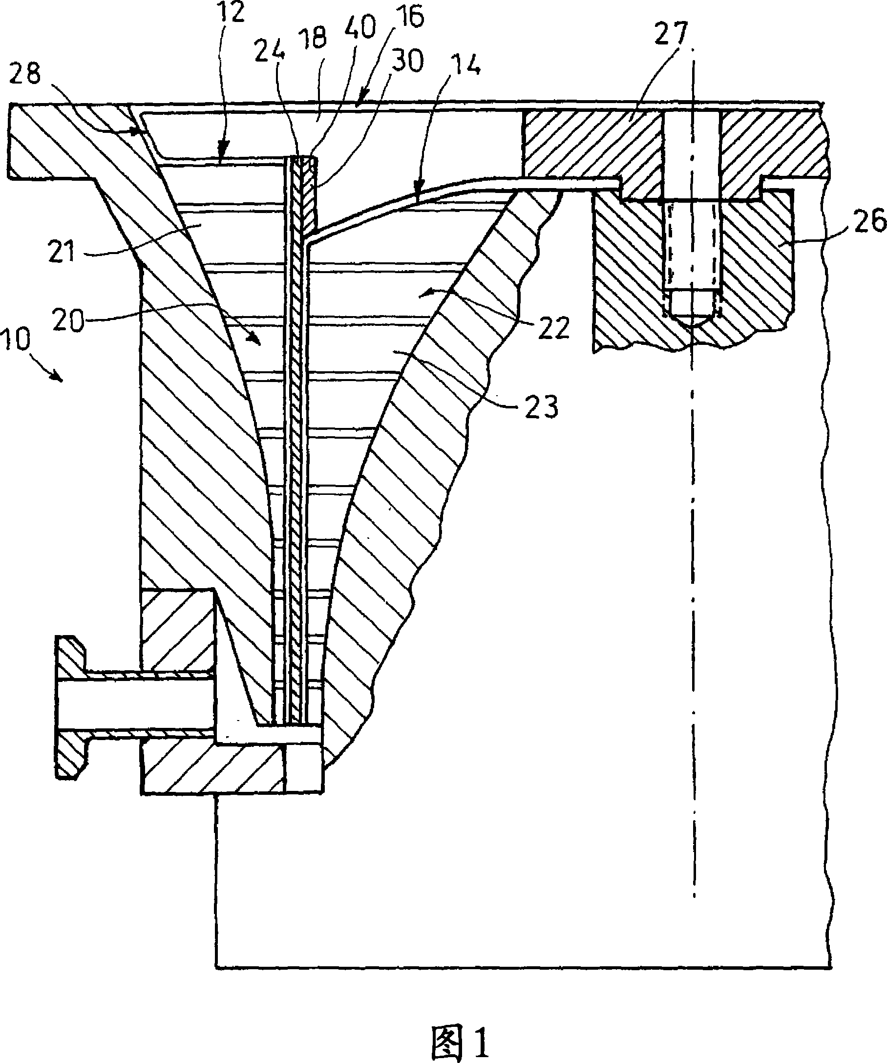
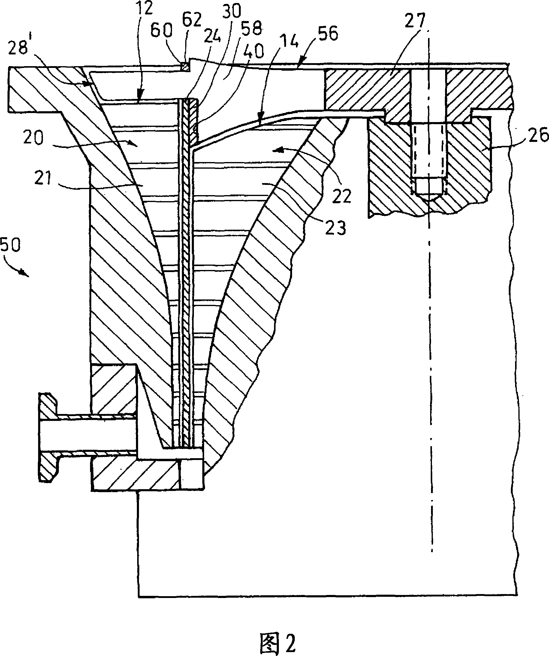
[0014] Figures 1 and 2 show Holwick vacuum pumps 10, 50 comprising two parallel Holwick pump stages 12, 14, respectively. On the inlet side, the two Holwick vacuum pumps 10, 50 include rotor impellers 28, 28', respectively, and the rotor impellers 28, 28' have a plurality of blades 18, 58, respectively.

[0015] The two Hallwick pump stages 12, 14 are basically composed of a radially outer pump stator 20, a radially inner pump stator 22, and a rotor tube 24 arranged between the two stators 20, 22, respectively. The inner and outer pump stators 20, 22 respectively include spiral thread grooves 21, 23, and the groove bottoms of the spiral thread grooves 21, 23 respectively taper radially toward the outlet.

[0016] The pump rotor 16 basically includes a shaft 26, a hub 27, a blade 18, a support ring 30, and a rotor tube 24, and the shaft 26 is supported by a rolling bearing and / or a magnetic bearing. The pump rotor 56 of the vacuum pump 50 shown in FIG. 2 further includes a second g...


PUM


Abstract

The invention relates to a Holweck vacuum pump comprising a pump rotor (16) with a rotating tube (24) and pump stators (12, 14), each having a screw-type threaded groove (21, 23) and being situated radially inside and radially outside the rotor tube (24), in addition to a rotor blade disc (28) comprising a support ring (30) that supports the rotor tube (24). The blades (18) of the blade disc have shoulders on the rotor side (40), which bear the support ring (30).

Description

Technical field [0001] The invention relates to a Holweck vacuum pump, which includes a pump rotor with a rotor tube. Background technique [0002] From WO 2004 / 055375 A1, a two-way Holwick vacuum pump is known, which includes pump stators on the radially inner side and radially outer side of the rotor tube, and the pump stators are respectively composed of spiral threaded grooves. In order to improve the performance of the pump, a rotor impeller is provided on the inlet side, and the rotor impeller includes a support ring that supports the rotor tube. The axial length of the support ring is greater than the axial length of the blade of the impeller, so that the support ring penetrates the blade, that is, divides the blade into two parts in the radial direction. A part of the support ring extends in the axial direction from the plane of the rotor blade. For example, the rotor tube is fastened to the cantilever part of the support ring by being attached to the outside of the suppo...

Claims


Application Information

Patent Timeline
IPC IPC(8): F04D19/04
CPCF04D29/023F04D19/044F05D2300/43F05D2300/603F04D19/04
Inventor 罗兰·布卢门塔尔拉尔夫·阿达米茨迪尔克·卡利施海因茨·恩伦德尔
Owner OERLIKON LEYBOLD VACUUM
Features
  • R&D
  • Intellectual Property
  • Life Sciences
  • Materials
  • Tech Scout
  • Unparalleled Data Quality
  • Higher Quality Content
  • 60% Fewer Hallucinations
Learn More