Light emitting device and light emitting object using the same

A light-emitting device and a technology of a light-emitting part, which are applied to semiconductor devices of light-emitting elements, components of lighting devices, cooling/heating devices of lighting devices, etc., and can solve complex installation structures, high energy absorption rates, and reduced lighting efficiency, etc. problem, achieve the effect of reducing power consumption and suppressing temperature rise

Inactive Publication Date: 2008-02-20
LITEHOUSE TECH CORP
View PDF1 Cites 23 Cited by
  • Summary
  • Abstract
  • Description
  • Claims
  • Application Information

AI Technical Summary

Problems solved by technology

Conventionally, paints containing white pigments such as titanium oxide have been used as reflective members of lighting fixtures such as fluorescent lamps. Lighting efficiency is correspondingly reduced
In addition, the use of reflective members complicates the mounting structure, etc.

Method used


Image

  • Light emitting device and light emitting object using the same
  • Light emitting device and light emitting object using the same
  • Light emitting device and light emitting object using the same

Examples


Embodiment 1

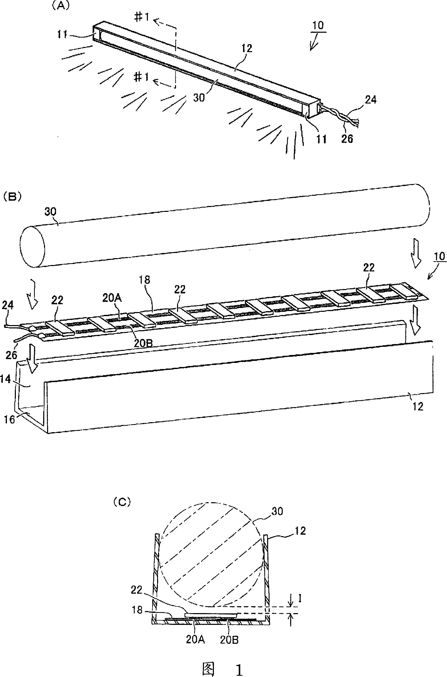
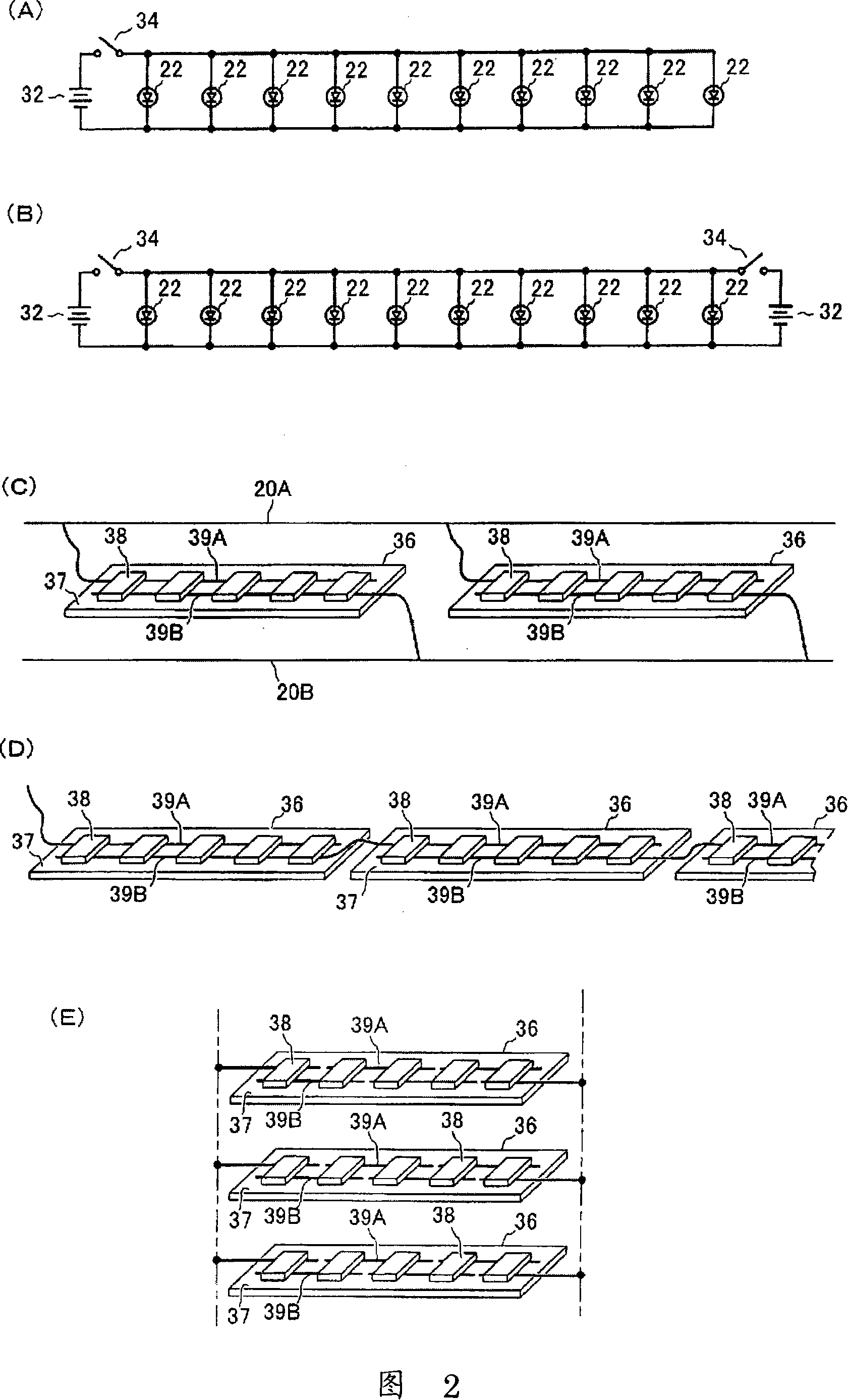
[0173] First, Embodiment 1 of the present invention will be described with reference to FIGS. 1 and 2 . 1(A) is a perspective view showing the appearance of this embodiment, (B) is an exploded perspective view thereof, and (C) is a cross-sectional view of #1-#1 of the above-mentioned (A). Fig. 2 is a circuit diagram of this embodiment. This embodiment is an embodiment in which the light-emitting device of the present invention is applied to linear lighting fixtures for various purposes. The light emitting device 10 has a structure in which an LED 22 as a light source and a rod-shaped transparent body 30 with a substantially circular cross section arranged close to the LED 22 are accommodated in a shade 12 having a substantially U-shaped cross section. End covers 11 are provided at both ends of the transparent body 30 as needed. As shown in Figure 1 (B) and (C), the front end of the open portion 14 of the above-mentioned lampshade 12 is a substantially U-shaped cross-section ...

Embodiment 2

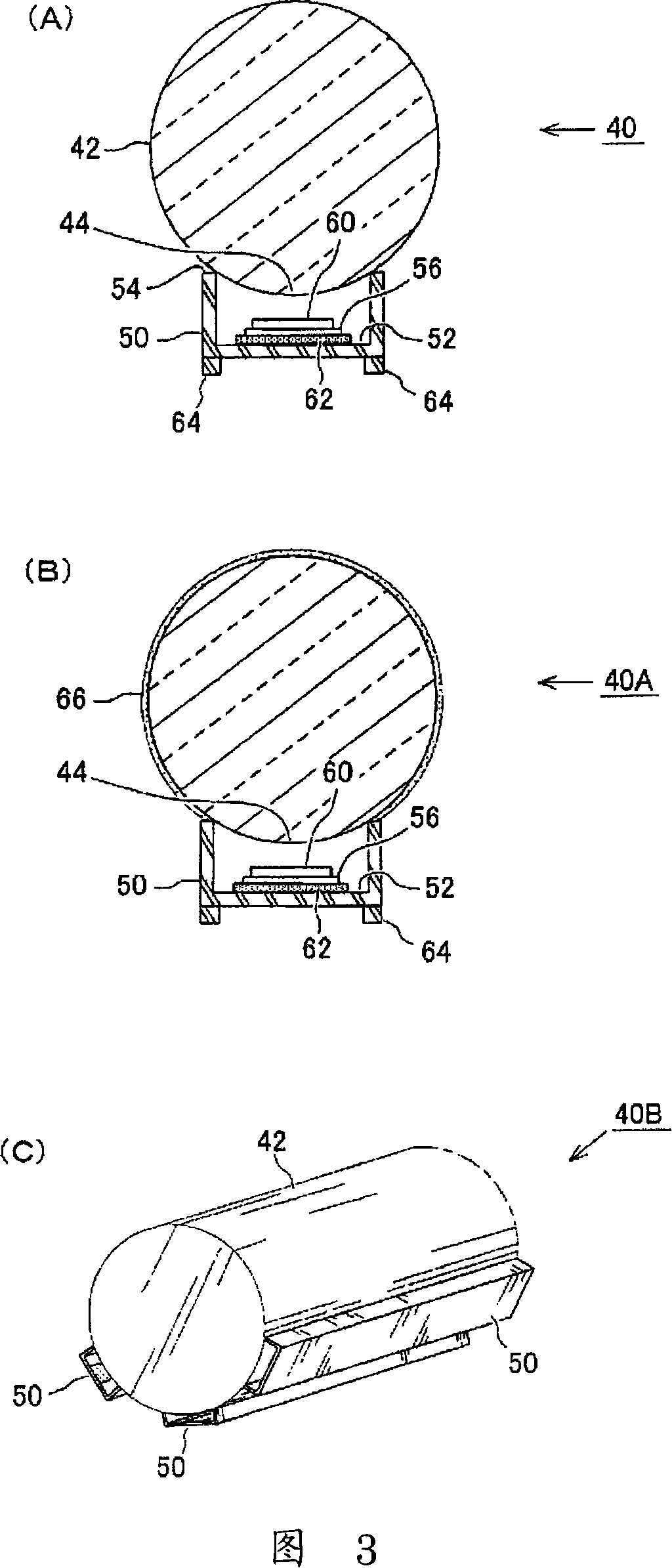
[0185]Next, Embodiment 2 of the present invention will be described with reference to FIG. 3 . 3(A) is a front sectional view of this embodiment, FIG. 3(B) is a front sectional view of a modification of this embodiment, and FIG. 3(C) is a perspective view of another modification. Similar to the first embodiment above, this embodiment is also an example of using a longer transparent body, but by more actively dissipating heat, a greater effect of suppressing temperature rise can be obtained. First, the light-emitting device 40 shown in FIG. 3(A) accommodates an LED 60 as a light source and a circuit board 56 provided with a plurality of LEDs 60 in a lampshade 50 having a substantially U-shaped cross section. The edge 54 of the upper end of the side surface of the lampshade 50 is attached so that the outer peripheral surface of the transparent body 42 contacts. In addition, the arrangement|positioning of the electrode pattern and LED60 on the said circuit board 56 is the same a...

Embodiment 3

[0191] Next, Embodiment 3 of the present invention will be described with reference to FIGS. 4 and 5 . The above-mentioned embodiments 1 and 2 use a linear transparent body, but in this embodiment, the transparent body is made into a ring shape. FIG. 4(A) is a plan view showing the appearance of this embodiment, and FIG. 4(B) is a cross-sectional view of #4-#4 in the aforementioned (A). Fig. 5 is a perspective view showing the structure when the transparent body is removed from the present embodiment.

[0192] The light-emitting device 70 of the present embodiment is a ring-shaped lighting fixture that can be arranged in any place. The lampshade 74 is configured to hold the outer peripheral surface of the transparent body 78 and is mounted on the fixing plate 72 , and LEDs 80A and 80B are provided inside the lampshade 74 as light sources for irradiating light to the transparent body 78 from the outside. As shown in FIG. 4(B), the cross-section of the transparent body 78 is s...


PUM


Abstract

The present invention relates to a light emitting device and a light emitting object using the light emitting device. The entire part of the light emitting device can emit light uniformly with sufficient brightness according to the purpose of use, in which a rise in temperature is suppressed and electric power consumption is reduced, and that can easily cope with a change in the entire shape and size. The light emitting device (10) is constructed from a bar-like transparent body (30) having a substantially circular cross-section, a light cover (12) installed on the outer periphery of the transparent body (30) and holding the outer periphery of the transparent body (30), and LEDs (22) arranged in the light cover (12) and introducing light into the transparent body (30). The LEDs (22) are disposed so as to keep a predetermined distance (I) from the surface of the transparent body (30). When the LEDs (22) emit light, the light enters into the transparent body (30) from many directions because of an airspace between the LEDs (22) and the transparent body (30), refracted and diffused by a lens effect of the transparent body (30), and emitted to the outside from an opening (14) of the light cover (12). When seen from the outside, the entire transparent body (30) emits light uniformly and brightly.

Description

technical field [0001] The present invention relates to a light-emitting device and a light-emitting object using the light-emitting device, more specifically, to a light-emitting device that guides light into a transparent object and the improvement of brightness and uniformity of light emission of a light-emitting object using the light-emitting device. Background technique [0002] Lighting fixtures such as fluorescent lamps used in homes, offices, hospitals, and other facilities are provided with reflective members on the back or side of the light source. Light from a light source (fluorescent lamp, incandescent lamp) is reflected in the desired lighting direction once it hits the above-mentioned reflective member, thereby providing soft light that has the effect of increasing the brightness of the lighting fixture and at the same time diffuses from the wide surface of the reflective member . Conventionally, paints containing white pigments such as titanium oxide have b...

Claims


Application Information

Patent Timeline
Patent Type & Authority Applications(China)
IPC IPC(8): F21S2/00F21V29/00F21L4/00F21Y101/02F21S9/02F21Y103/00F21S8/04F21K9/20F21V29/506F21V29/71F21V29/74F21V29/87F21Y103/10F21Y115/10
CPCH01L2924/0002F21S4/008F21V5/043F21S4/28H01L2924/00
Inventor 大门末吉
Owner LITEHOUSE TECH CORP
Why Eureka
Try Eureka