Elevator door device
A door device and elevator technology, which is applied in the field of elevator door devices, can solve the problems of abnormal sound and increased door opening and closing resistance, and achieve the effects of suppressing abnormal sound, reducing opening and closing resistance, and suppressing the generation of abnormal sound
- Summary
- Abstract
- Description
- Claims
- Application Information
AI Technical Summary
Problems solved by technology
Method used
Image
Examples
Embodiment approach 1
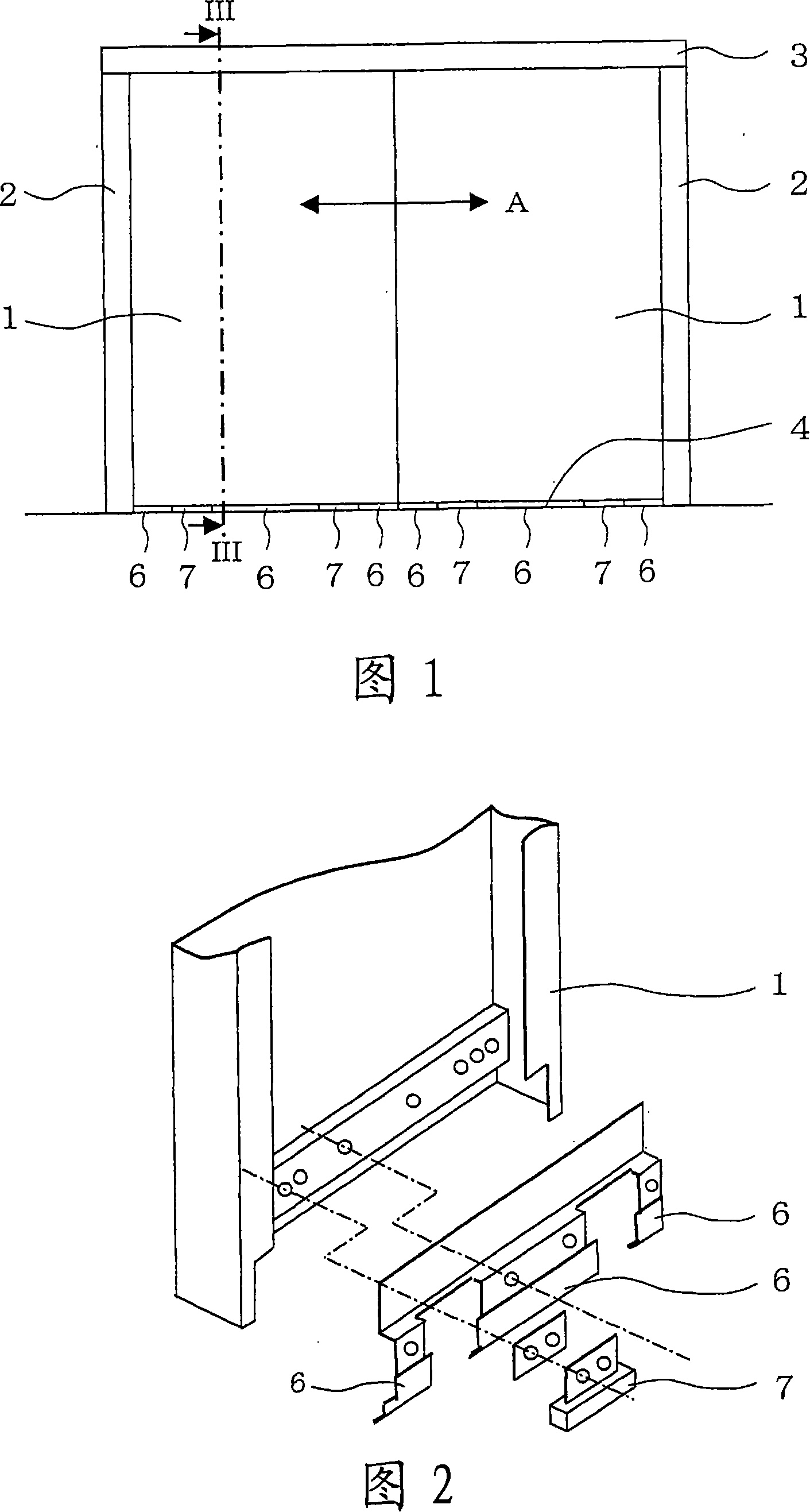
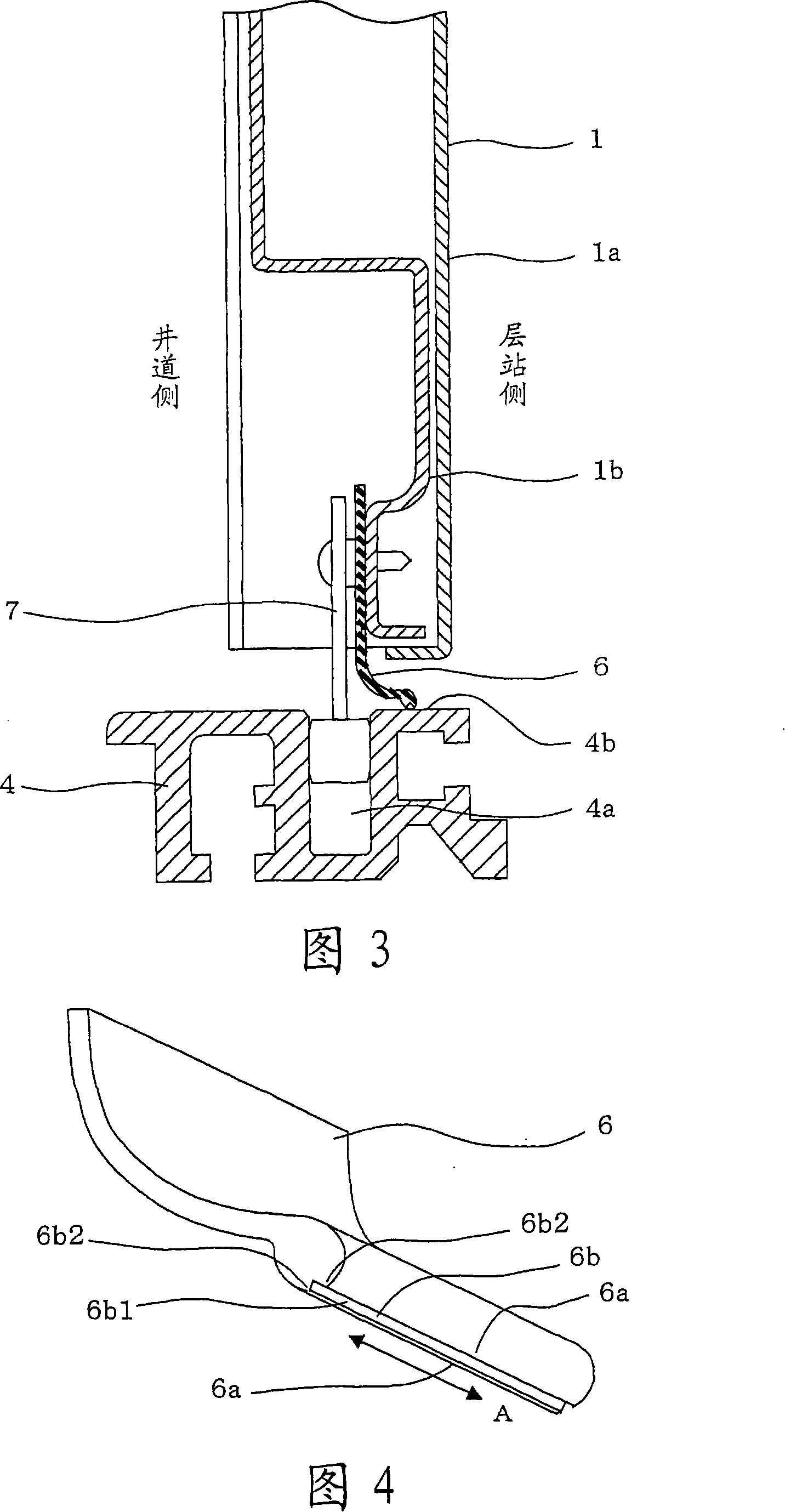
[0027] Next, Embodiment 1 of the present invention will be described with reference to FIGS. 1 to 4 . Fig. 1 is a view of a hall-side door and a door frame of a double-door-type elevator viewed from the hall side, Fig. 2 is an exploded perspective view of one door in Fig. 1 viewed from the hoistway side, and Fig. 3 is along the arrow direction Looking at the longitudinal cross-sectional view of the main part of the cross section taken along the line III-III in FIG. 1 , FIG. 4 is an enlarged perspective view of the airtight member in FIG. 3 .
[0028] In FIGS. 1 to 4 , in the elevator hall, between the hall door 1 and the door casing vertical frame 2 , between the hall door 1 and the door casing upper frame 3 , and between the hall door 1 and the door casing There is a gap between the landing sills 4, so the fire barrier and smoke barrier properties are poor. Then, in order to improve smoke barrier property and fire barrier property, the airtight member is arrange|positioned i...
Embodiment approach 2
[0037] Next, Embodiment 2 of the present invention will be described with reference to FIGS. 5 and 6 . FIG. 5 is a longitudinal sectional view of a main part, and FIG. 6 is an enlarged perspective view of the airtight member in FIG. 5 .
[0038] In the second embodiment of the present invention, as the low friction portion 6b, on the pressure contact surface 6a of the airtight member 6 that is in pressure contact with the surface 4b on the ground side, in the opening and closing direction A of the door 1 at a predetermined value A plurality of ridges 6c extending in the direction perpendicular to the opening and closing direction A of the door 1, that is, in the intersecting direction, are provided at intervals.
[0039] In addition, the above-mentioned protruding lines 6c are formed at the same time when the above-mentioned airtight member 6 is formed of rubber.
[0040] With the above configuration, as in the case of the above-described first embodiment of the present inven...
Embodiment approach 3
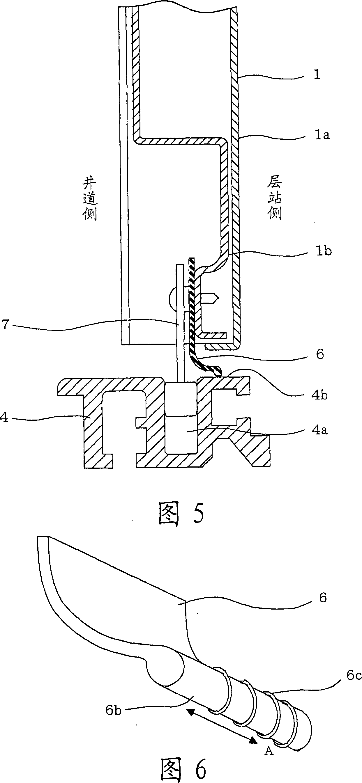
[0043] Next, Embodiment 3 of the present invention will be described with reference to FIGS. 7 and 8 . FIG. 7 is a longitudinal sectional view of a main part, and FIG. 8 is an enlarged perspective view of the airtight member in FIG. 7 .
[0044] The third embodiment of the present invention is configured such that, as the low friction portion 6b, protrusions 6d are dispersed on a crimping surface 6a of the airtight member 6 that is in pressure contact with the surface 4b on the ground side.
[0045] In addition, the projection 6d is formed at the same time when the airtight member 6 is formed of rubber, or formed by coating or the like.
[0046] With the above configuration, as in the case of the above-described first embodiment of the present invention, by reducing the contact area between the lower airtight member 6 of the landing door and the landing sill 4, the adhesion of the airtight member 6 and the sill 4 is prevented. The resulting increase in travel resistance. In ...
PUM
 Abstract
Description
Claims
Application Information
 - R&D
- Intellectual Property
- Life Sciences
- Materials
- Tech Scout
- Unparalleled Data Quality
- Higher Quality Content
- 60% Fewer Hallucinations
Browse by: Latest US Patents, China's latest patents, Technical Efficacy Thesaurus, Application Domain, Technology Topic, Popular Technical Reports.
© 2025 PatSnap. All rights reserved.Legal|Privacy policy|Modern Slavery Act Transparency Statement|Sitemap|About US| Contact US: help@patsnap.com


