Elevator door device

A door device and elevator technology, which is applied in the field of elevator door devices, can solve the problems of increased door opening and closing resistance and abnormal sound, and achieve the effect of reducing opening and closing resistance and suppressing abnormal sound

Inactive Publication Date: 2011-02-02
MITSUBISHI ELECTRIC CORP
View PDF3 Cites 0 Cited by
  • Summary
  • Abstract
  • Description
  • Claims
  • Application Information

AI Technical Summary

Problems solved by technology

[0006] In Patent Documents 1 to 3, Patent Document 3 discloses a door device for an elevator in which a flexible airtight member extending in the opening and closing direction of the door body is pressed against the ground by virtue of its flexibility. The airtight member slides on the ground side surface with the opening and closing of the door in the state of being in pressure contact with the ground side surface. In the door device of such an elevator, the airtight member is attached to the sill of the door, and when the door is opened and closed, an increase in door opening and closing resistance and abnormal noise are generated, or when the door is opened and closed, due to The stick slip phenomenon caused by the sliding of the airtight parts relative to the sill produces abnormal sound, or when the gap between the door and the sill becomes smaller when the door is opened and closed, the air The airtight parts are crushed, and the contact area between the sill and the airtight parts becomes larger, which increases the opening and closing resistance of the door, or makes an abnormal sound when the door is opened and closed.

Method used


Image

  • Elevator door device
  • Elevator door device
  • Elevator door device

Examples


Embodiment approach 1

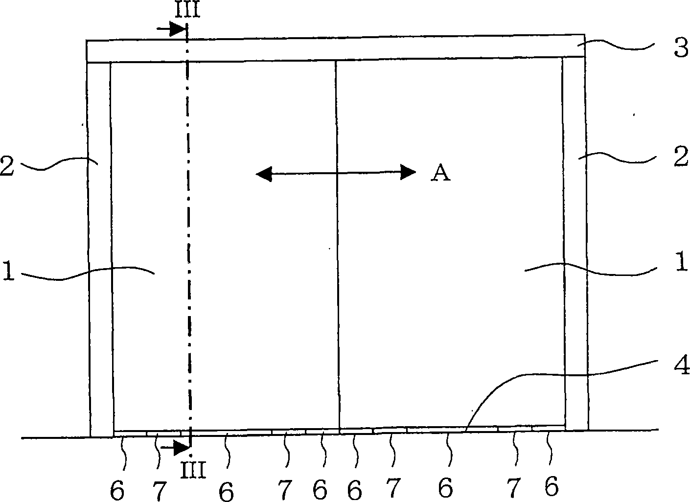
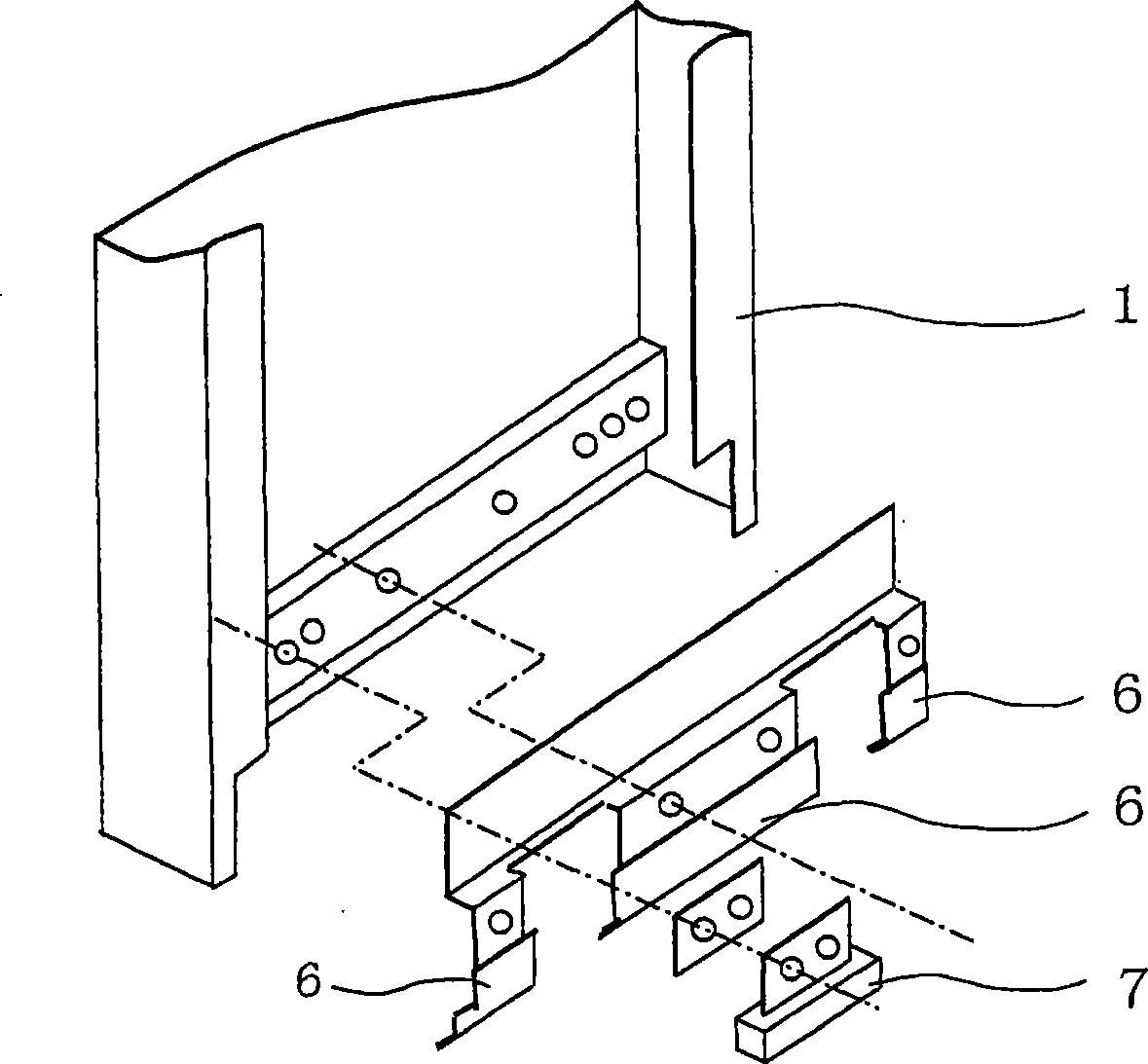
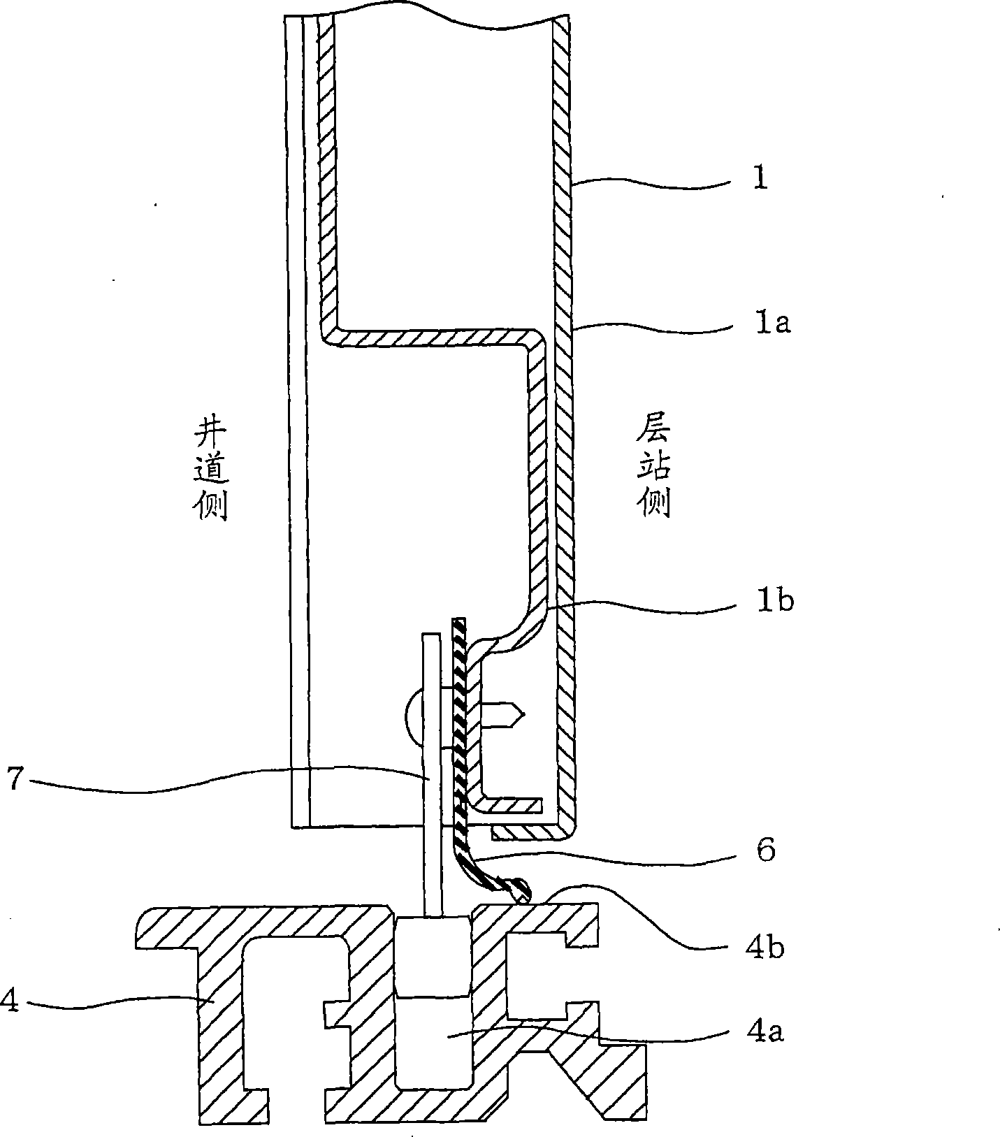
[0028] The following is based on Figure 1 ~ Figure 4 Embodiment 1 of the present invention will be described. figure 1 This is a diagram of the door and its frame on the landing side of a double-door type elevator viewed from the landing side, figure 2 It is viewed from the side of the shaft figure 1 An exploded perspective view of a door in , image 3 is looking in the direction of the arrow figure 1 A longitudinal sectional view of the main part of the section at the line III-III, Figure 4 yes image 3 An enlarged perspective view of the airtight components in .

[0029] exist Figure 1 ~ Figure 4 Among them, in the elevator landing, because between the landing door 1 and the vertical frame 2 of the door pocket, between the landing door 1 and the upper frame 3 of the door pocket, and between the landing door 1 and the landing sill 4 There is a gap between them, so the fire resistance and smoke resistance are poor. Then, in order to improve the smoke-proof property...

Embodiment approach 2

[0038] The following is based on Figure 5 and Figure 6 Embodiment 2 of the present invention will be described. Figure 5 is a longitudinal sectional view of the main part, Figure 6 yes Figure 5 An enlarged perspective view of the airtight components in .

[0039] In Embodiment 2 of the present invention, as the low-friction portion 6b, on the pressure-contact surface 6a of the airtight member 6 that is in pressure contact with the surface 4b on the ground side, a predetermined amount is provided in the opening and closing direction A of the door 1. A plurality of ridges 6 c extending in a direction perpendicular to the opening and closing direction A of the door 1 , that is, in a direction intersecting, are provided at intervals.

[0040] In addition, the above-mentioned protruding lines 6c are molded at the same time when the above-mentioned airtight member 6 is molded from rubber.

[0041] With the above structure, as in the case of Embodiment 1 of the present inve...

Embodiment approach 3

[0044] The following is based on Figure 7 and Figure 8 Embodiment 3 of the present invention will be described. Figure 7 is a longitudinal sectional view of the main part, Figure 8 yes Figure 7 An enlarged perspective view of the airtight components in .

[0045] Embodiment 3 of the present invention is configured such that, as the low-friction portion 6b, projections 6d are dispersed on the pressure-contact surface 6a of the airtight member 6 that is in pressure contact with the surface 4b on the ground side.

[0046] In addition, the above-mentioned protrusion 6d is molded simultaneously when the above-mentioned airtight member 6 is molded from rubber, or is molded by coating or the like.

[0047] With the above structure, as in the case of Embodiment 1 of the present invention described above, the adhesion of the airtight member 6 and the sill 4 is prevented by reducing the contact area between the lower airtight member 6 of the landing door and the landing sill 4 ...


PUM


Abstract

A door device for an elevator, in which a flexible air-tight member (6) extended in the opening / closing direction (A) of a door body (1b) is attached to the door body (1b) so as to be in pressed contact with a floor-side surface (4b) and, as the door (1) is opened and closed, the air-tight member (6) slides on the floor-side surface (4b) while being in pressed contact with the floor-side surface (4b). A low friction section (6b) is formed on that surface (6a) of the air-tight member (6) with which the floor-side surface (4b) is in pressed contact.

Description

technical field [0001] The present invention relates to an elevator door apparatus in which a flexible airtight member extending in the opening and closing direction of a door main body is pressed against a surface on the ground side by virtue of its flexibility. Attached to the door main body, the airtight member slides on the ground-side surface as the door is opened and closed in a state of being pressure-contacted to the ground-side surface. Background technique [0002] In Patent Documents 1 to 3, various airtight members are proposed that block the gap between the elevator door and its mounting frame to block smoke. [0003] Patent Document 1: Japanese Patent Laid-Open No. 2004-083145 [0004] Patent Document 2: Japanese Patent Application Laid-Open No. 7-157254 [0005] Patent Document 3: Specification of Japanese Patent Laid-Open No. 2004-323222 [0006] In Patent Documents 1 to 3, Patent Document 3 discloses a door device for an elevator in which a flexible airti...

Claims


Application Information

Patent Timeline
Patent Type & Authority Patents(China)
IPC IPC(8): B66B13/30
CPCB66B13/301
Inventor 铃木稔也饭田真司近藤丈治田中繁之
Owner MITSUBISHI ELECTRIC CORP
Why Eureka
Try Eureka