Supercharge Your Innovation With Domain-Expert AI Agents!

Damping device for an output shaft in a gearbox

The technology of a shock absorbing device and a gear box is applied in the direction of supporting devices, drilling equipment, drilling equipment and methods, etc.

Active Publication Date: 2008-02-27
EPIROC ROCK DRILLS AB
View PDF0 Cites 5 Cited by
  • Summary
  • Abstract
  • Description
  • Claims
  • Application Information

AI Technical Summary

Problems solved by technology

[0005] According to the invention, the problem that the load acting on the output shaft in a gearbox with play during positioning may be transmitted between the gear tooth flanks is solved by providing a damping device for the output shaft in the gearbox for positioning, Wherein, the damping device includes a brake acting on the output shaft of the gearbox, and the brake acts as a shock absorber for the movement of the output shaft

Method used


Image

  • Damping device for an output shaft in a gearbox
  • Damping device for an output shaft in a gearbox
  • Damping device for an output shaft in a gearbox

Examples


Embodiment Construction

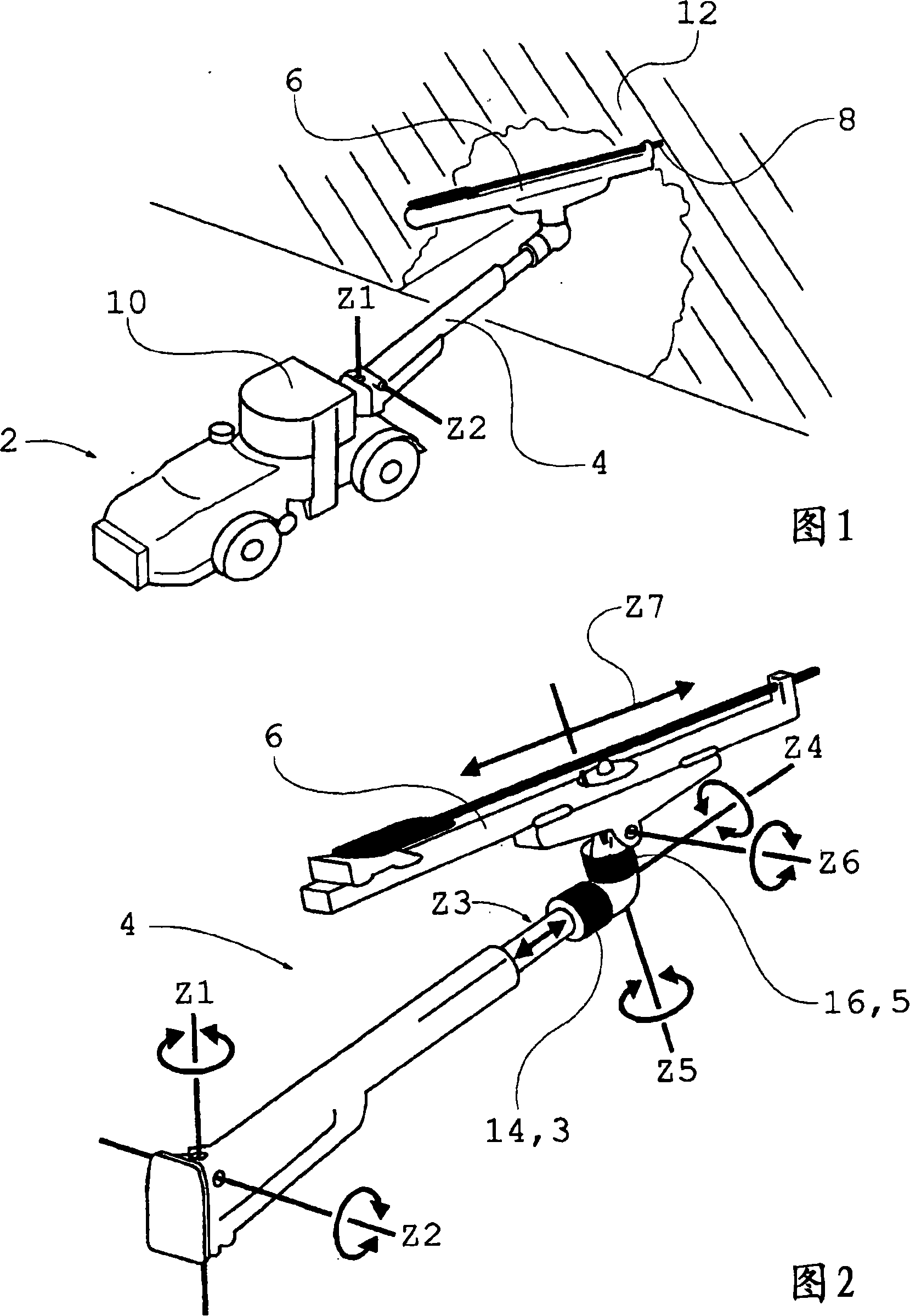
[0013] FIG. 1 shows a schematic view of a rock drilling rig 2 comprising a boom 4 , a thruster 6 and a cutting head 8 . The rock drilling rig 2 can be remotely controlled by an operator via a cable (not shown) or by wireless means, but can also be controlled by an operator located in an operating cabin 10 on the rock drilling rig 2 . The operator can control the rock drilling machine 2 manually, automatically or semi-automatically. When an operator wants to use the rock drill 2 to drill a hole in rock 12, it is important that the cutting head 8 of the pusher 6 can be positioned in the correct position and in the correct angular orientation relative to the rock 12 in order to produce the desired hole , especially when several holes are to be drilled into the rock 12 parallel to each other, such as occurs when drilling a tunnel through a mountain.

[0014] FIG. 2 shows a schematic diagram of the drill boom 4 on the rock drilling machine 2 in FIG. 1 . According to this embodime...


PUM


Abstract

The invention relates to a damping device for an output shaft (26) in a gearbox (14, 16), where the gearbox (14, 16) is arranged for rotation of a rotational degree of freedom (Z4,Z5) in a rock-drilling rig (2), and thus for positioning of the same, and where the damping device (18) comprises a brake (38) that acts on the output shaft (26) of the gearbox (14, 16), which brake (38) acts as an oscillation damper for the movement of the output shaft (26), whereby a gearbox (14, 16) with play can be used for applications that require a high degree of precision such as positioning, e.g. measuring a position for a drill hole. The invention also relates to a gearbox (14, 16) and a rock-drilling rig (2) with damping device (18), respectively.

Description

technical field [0001] The invention relates to a damping device in a rock drilling machine. The invention also relates to a gearbox and a rock drilling rig with damping means. Background technique [0002] On modern rock drilling rigs the position of the boom is measured so that it is possible to use automatic control to drill the hole in the correct part of the rock. When measuring the position of the drilled hole, measure the angle at each joint of the drill arm and at any telescopic movement of the drill arm. The drill boom usually has 5 to 6 joints, for which measurements must be made with a high degree of precision in order to be able to calculate where the hole will be drilled. [0003] To obtain the rotation at the boom joint, a gearbox can be used, whereby it is possible to choose between using a special gearbox without play, expensive, or a standard gearbox with play, cheap. [0004] A problem that arises when using a gearbox with backlash to locate the boom joi...

Claims


Application Information

Patent Timeline
Patent Type & Authority Applications(China)
IPC IPC(8): E21B15/04
CPCE21B7/025
Inventor F·萨夫
Owner EPIROC ROCK DRILLS AB
Features
  • R&D
  • Intellectual Property
  • Life Sciences
  • Materials
  • Tech Scout
  • Unparalleled Data Quality
  • Higher Quality Content
  • 60% Fewer Hallucinations
Learn More