Link tooth saw

A technology of chain saws and sprockets, which is applied in the direction of chain saws, sawing equipment, sawing machine devices, etc., which can solve the problems of increased manufacturing cost, increased number of parts, and poor operability of locking mechanisms, and achieves simple structure and cost suppression Ascending, sequentially simple effects

Active Publication Date: 2008-03-05
MAKITA CORP
View PDF1 Cites 6 Cited by
  • Summary
  • Abstract
  • Description
  • Claims
  • Application Information

AI Technical Summary

Problems solved by technology

[0004] In the chain saw with the above-mentioned locking structure, when turning the operation knob from the locked state, it is necessary to lift the lever to release the lock, and then turn the knob. Locking generally requires two different operations: tilting or raising the lever and turning the knob, and the operability deteriorates.
[0005] In addition, the use of the lever also complicates the structure, resulting in an increase in the number of parts and an increase in the manufacturing cost of the lock mechanism

Method used


Image

  • Link tooth saw
  • Link tooth saw
  • Link tooth saw

Examples


Embodiment Construction

[0019] Hereinafter, embodiments of the present invention will be described based on the drawings.

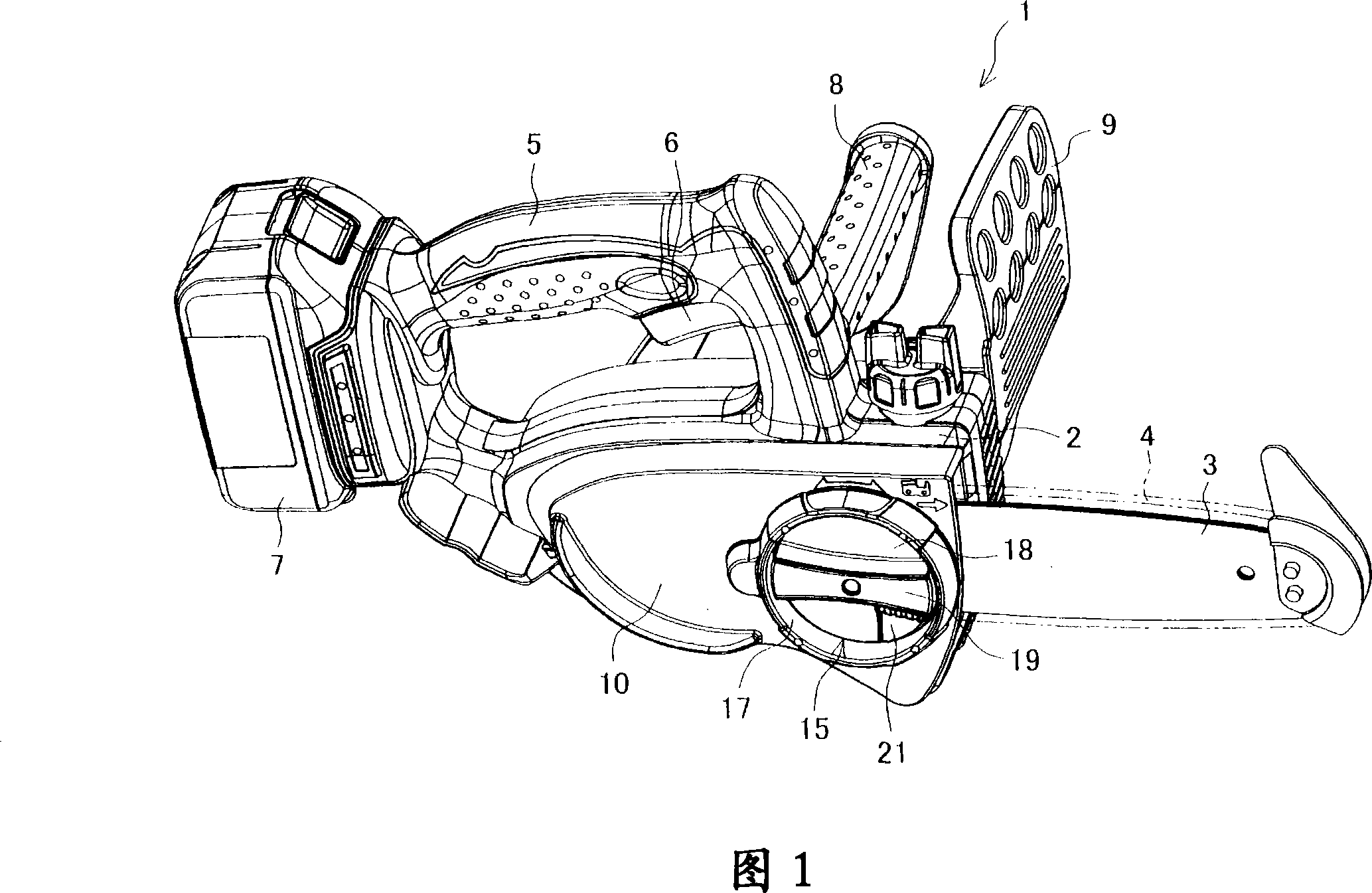
[0020] 1 is a perspective view showing an example of a chain saw. In this figure, the main body 2 of the chain saw 1 has a built-in motor and its speed reduction mechanism, and a sprocket and a guide plate 3 (not shown) are provided on the side of the main body 2. The sprocket is arranged on the output shaft of the reduction mechanism, and the guide plate 3 is in the shape of a long disc, which is in front of the sprocket (the right side in Fig. 1 ) and protrudes forward than the main body 2, and 3 sheets are wound around the sprocket and the guide plate. A saw chain 4 is provided, and the saw chain 4 is rotated along the periphery of the guide plate 3 along with the rotation of the sprocket, thereby cutting the object to be cut. A handle 5 is extended above the main body 2, a switch lever (trigger) 6 for switching the motor is provided on the handle 5, and a battery pack 7 as a...


PUM


Abstract

The invention provides a chain saw for fixing and releasing fixtion of a guide plate through a simple operation. An operation handle (15) of the chain saw is used for fixing and releasing fixtion of a guide plate (3), which is provided with a lock knob (21) being in and out relative to the operation handle, under a normal state, the lock knob is loaded a force by a helical spring (26) in the protrudent direction of the operation handle, which is arranged at following position, at the position, the lock knob is pushed when gripping the operation handle, meanwhile, an accepting part (17) of theoperation handle is provided a plurality of protuberances (31, 31...), the protuberances allow the lock knob to slide when the operation handle is rotated to the fixing side of the guide plate (3), and limit the lock knob to slide when the operation handle is rotated to the fixtion releasing side of the guide plate, need to push the lock knob only when rotating the operation handle while releasing fixtion of the guide plate.

Description

technical field [0001] The invention relates to a chain saw. The sprocket is arranged on the main body and is driven to rotate. The guide plate protrudes toward the front of the main body. A saw chain is stretched on the sprocket and the guide plate. Rotate along the periphery of the guide plate to cut off the cut object. Background technique [0002] On the chain saw, there is a sprocket and a guide plate on the side of the main body, wherein the sprocket is driven by a motor or an engine to rotate, the guide plate is in the shape of a plate protruding forward, and a saw chain is stretched around the sprocket and the guide plate. By making the saw The chain rotates along the periphery of the guide plate along with the rotation of the sprocket, so that the saw chain can cut off the cut object. [0003] In this chain saw, in order to adjust the tension of the saw chain or replace the saw chain, it is necessary to be able to adjust the fixed position of the guide plate relati...

Claims


Application Information

Patent Timeline
Patent Type & Authority Applications(China)
IPC IPC(8): B23D57/02B27B17/00B28D1/08
CPCB25F5/02
Inventor 伊藤亮介
Owner MAKITA CORP
Why Eureka
Try Eureka