Cloth device and method

A fabric distributing device and fabric technology, applied in the direction of supply devices, manufacturing tools, etc., can solve the problems of low fabric efficiency, and achieve the effect of improving work efficiency, continuous lines, and beautiful surface patterns

Inactive Publication Date: 2008-03-05
KEDA INDUSTRIAL GROUP CO LTD
View PDF0 Cites 11 Cited by
  • Summary
  • Abstract
  • Description
  • Claims
  • Application Information

AI Technical Summary

Problems solved by technology

[0007] The purpose of the present invention is to provide a cloth distribution device and a cloth distribution method, which can effectively solve the technical defects of the prior art such as low cloth efficiency.

Method used


Image

  • Cloth device and method
  • Cloth device and method
  • Cloth device and method

Examples


Embodiment Construction

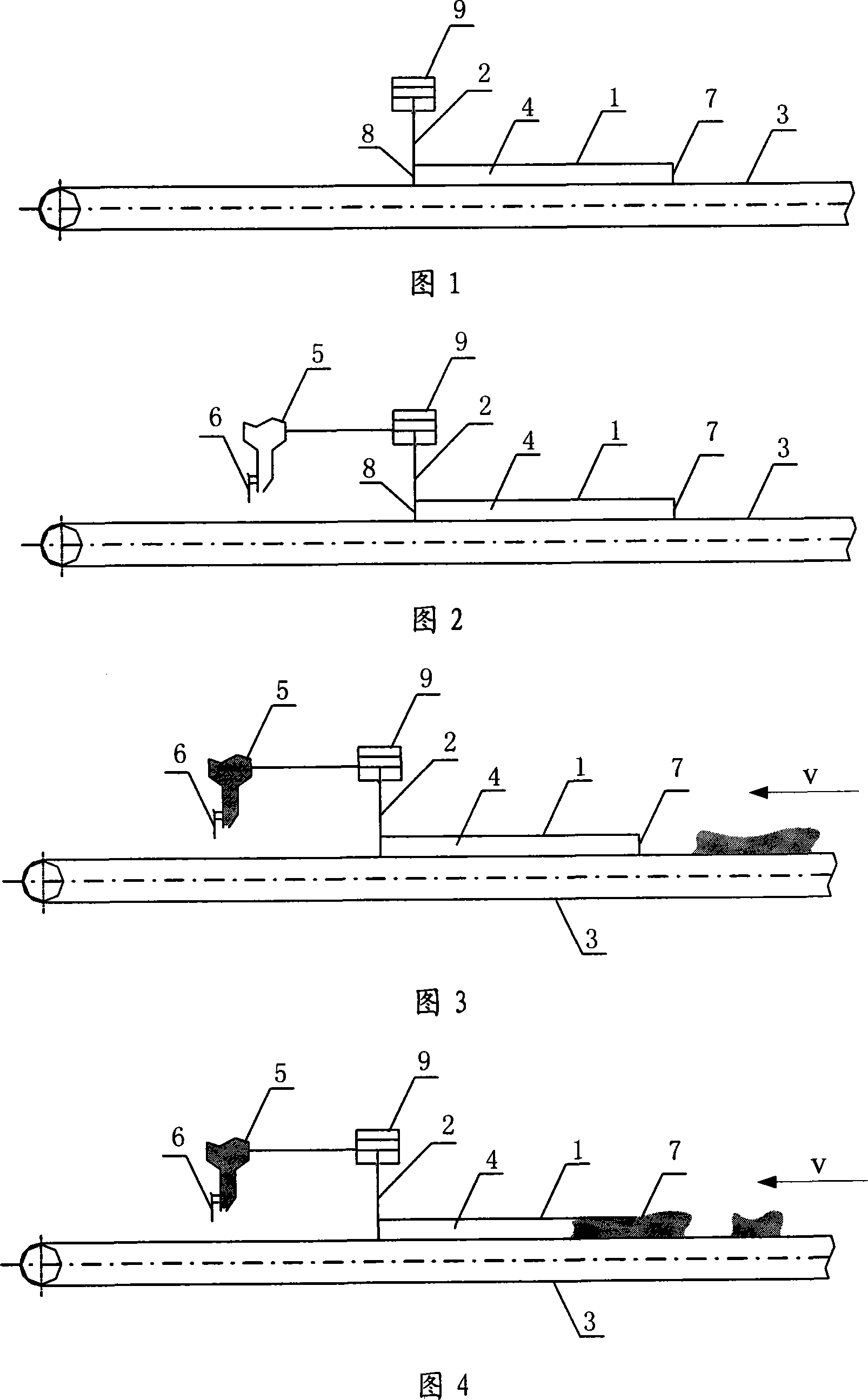
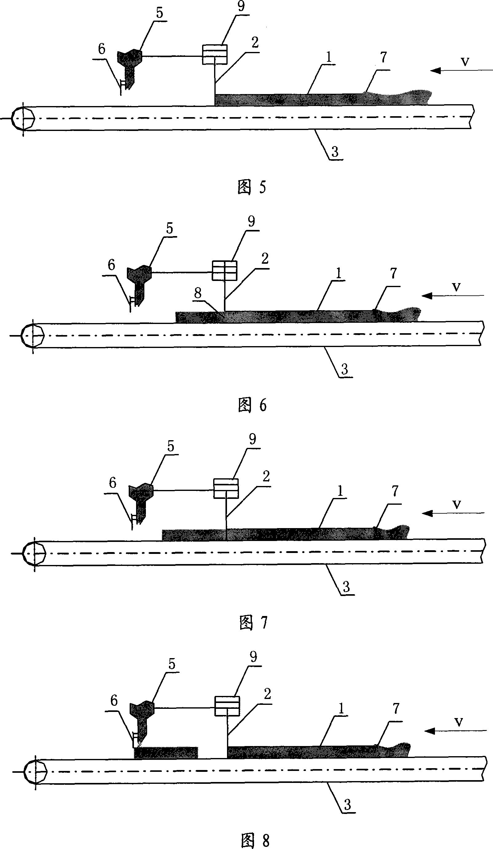
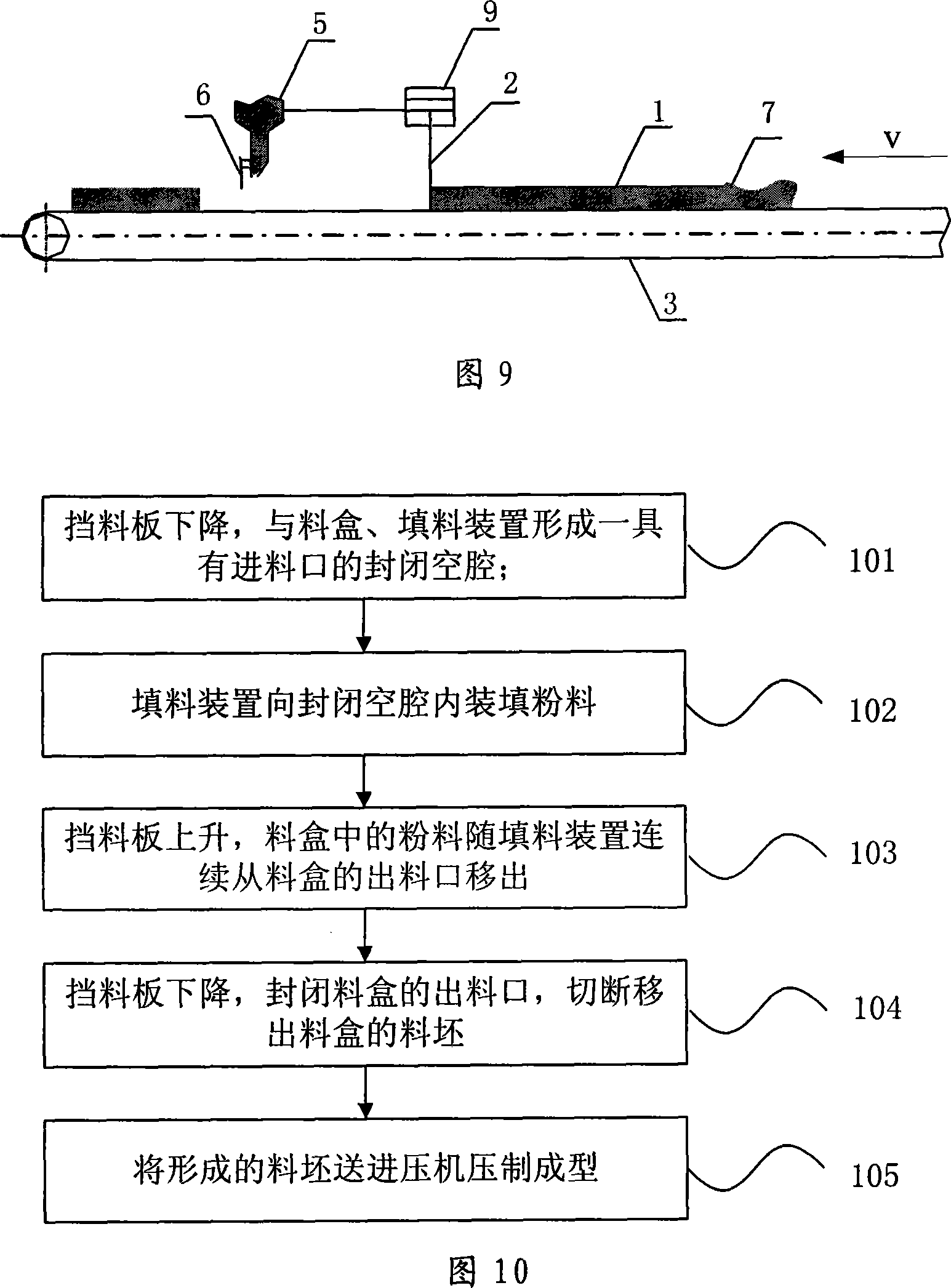
[0037] Fig. 1 is a schematic structural view of the distributing device of the present invention. As shown in FIG. 1 , the main structure of the material distribution device includes a material box 1 , a material baffle plate 2 , and a filling device 3 . Both ends of the material box 1 are provided with openings, the material inlet 7 is used for feeding materials, and the material outlet 8 is used for material discharge; the material box 1 is buckled on the surface of the filling device 3 and does not move with the filling device 3; the baffle plate 2. It is set at the outlet 8 of the material box 1, and can move vertically up and down. When it moves downward and closes the output, it can form a closed space with the material inlet 7 together with the material box 1 and the filling device 3. Cavity 4; filling device 3 is used to fill powder into the closed cavity 4;

[0038] Specifically, the material box 1 is a rectangular body composed of two side plates and a top plate. T...


PUM

PropertyMeasurementUnit
speedaaaaaaaaaa

Abstract

The present invention relates to material distributing mechanism and process. The mechanism includes one material box with material inlet and material outlet and fixed on the surface of one stuffing mechanism; one material keeping plate set to the material outlet of the material box capable of moving vertically and forming one closed cavity with material inlet together with the material box and the stuffing mechanism, and one stuffing mechanism for filling powdered material to the closed cavity and conveying formed material blank. The process includes the following steps: descending the material keeping plate for forming one cavity, filling powdered material to the cavity with the stuffing mechanism, ascending the material keeping plate to discharge the powdered material from the material box through the material outlet, descending the material keeping plate to shut up the material outlet and cutting and shifting out the material blank, and conveying the material blank to the press.

Description

technical field [0001] The invention relates to a distributing device and a distributing method for ceramic tile production, in particular to a distributing device and a distributing method for distributing materials in a horizontal direction. Background technique [0002] The production of ceramic tiles mainly includes processes such as cloth, pressing, drying and sintering, among which cloth is an important process. [0003] Fig. 12 is a schematic diagram of the structure of an existing vertical material distribution device. The structure is as follows: four separable material boxes 1 are respectively arranged on the four tables of the turntable 10. Turn over to a horizontal position; the material box 1 is provided with a material box pressurizing device 12, which is used to press the material box 1 so that it is close to the turntable; the upper side of the turntable 10 is provided with a filling device 3, which is used to feed the vertically placed material box 1 Medium...

Claims


Application Information

Patent Timeline
Patent Type & Authority Applications(China)
IPC IPC(8): B28B13/02
Inventor 武桢李绍勇李高明
Owner KEDA INDUSTRIAL GROUP CO LTD
Why Eureka
Try Eureka