
Pneumatic motor

An air motor and cylinder technology, which is applied to machines/engines, rotary piston engines, fluid pressure actuating devices, etc., can solve the problems of difficulty in production and processing, large volume and weight of air motors, and bulky equipment, and achieves a lightweight, compact appearance. Weight and volume reduction, flexible handling and ease of use

Active Publication Date: 2008-03-05
郑雪梅
View PDF0 Cites 2 Cited by
  • Summary
  • Abstract
  • Description
  • Claims
  • Application Information

AI Technical Summary

Problems solved by technology

[0002] The vane air motor is a power device widely used in various pneumatic tools and pneumatic machinery. The existing air motor, as shown in Figures 1 and 2, includes a main body 11 and a cylinder lower seat 12 installed in the main body 11, Cylinder 13, blade 14, pneumatic rotor 15 and cylinder upper seat 16, described cylinder lower seat 12 and cylinder upper seat 16 are fixed on the two ends of described cylinder 13, and described pneumatic rotor 15 is placed in it, and on described pneumatic rotor 15 A blade groove 151 for inserting the blade 14 is provided, and two bearings are respectively arranged in the cylinder lower seat 12 and the cylinder upper seat 16, and the inner circumference of the bearing 17 is concentric with the outer circumference of the lower seat 12 or the upper seat 16. , in order to leave an air gap 18 for gas circulation between the pneumatic rotor 15 and the cylinder, the inner and outer circumferences of the cylinder 13 are eccentric structures, which lead to unequal thickness of the cylinder wall, which not only brings problems to production and processing. Difficulty, and make the volume and weight of the entire air motor larger, and therefore make the air tool equipment using this motor relatively heavy

Method used


Image

  • Pneumatic motor
  • Pneumatic motor
  • Pneumatic motor

Examples


Embodiment Construction

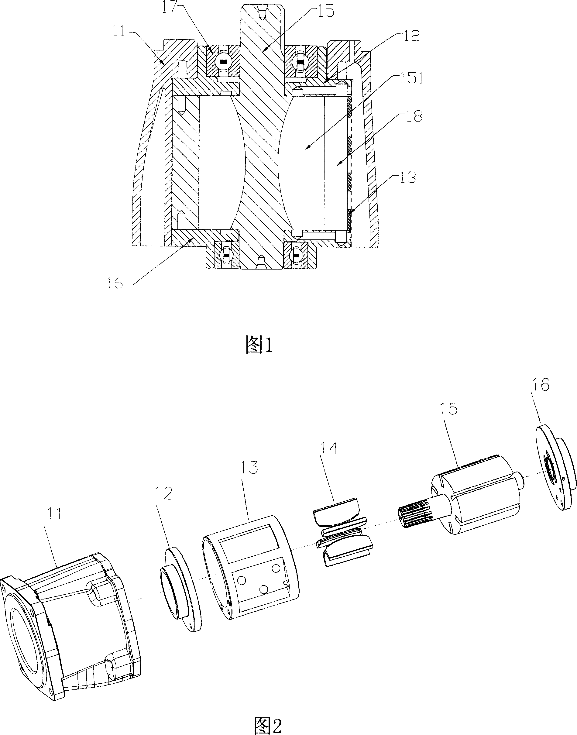
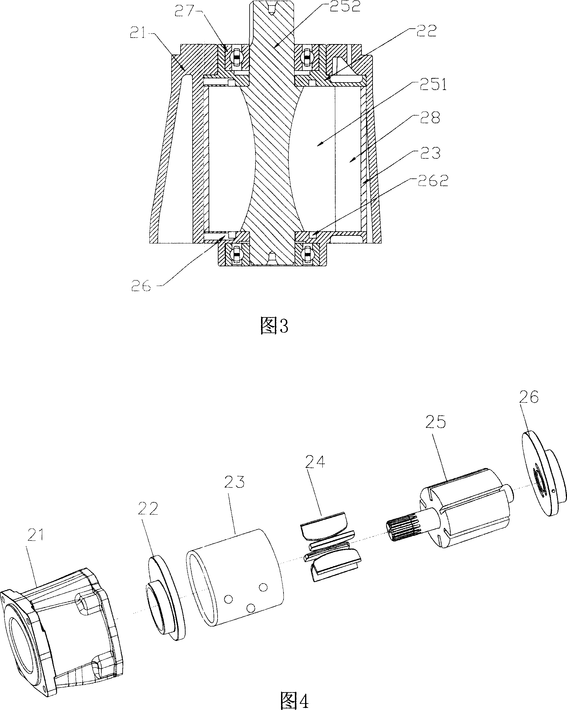
[0021] As shown in Figures 3, 4, and 6, it is a preferred embodiment of the present invention, including a main body 21 and a cylinder lower seat 22, a cylinder 23, blades 24, a pneumatic rotor 25 and an upper cylinder seat 26 installed in the main body 21, The cylinder lower seat 22 and the cylinder upper seat 26 are fixed at both ends of the cylinder 23, the pneumatic rotor 25 is placed therein, and the pneumatic rotor 25 is provided with blade grooves 251 for inserting the blades 24. Two bearings 27 are respectively arranged in the cylinder lower seat 22 and the cylinder upper seat 26 for fixing the rotor shaft 252 of the pneumatic rotor 25 .

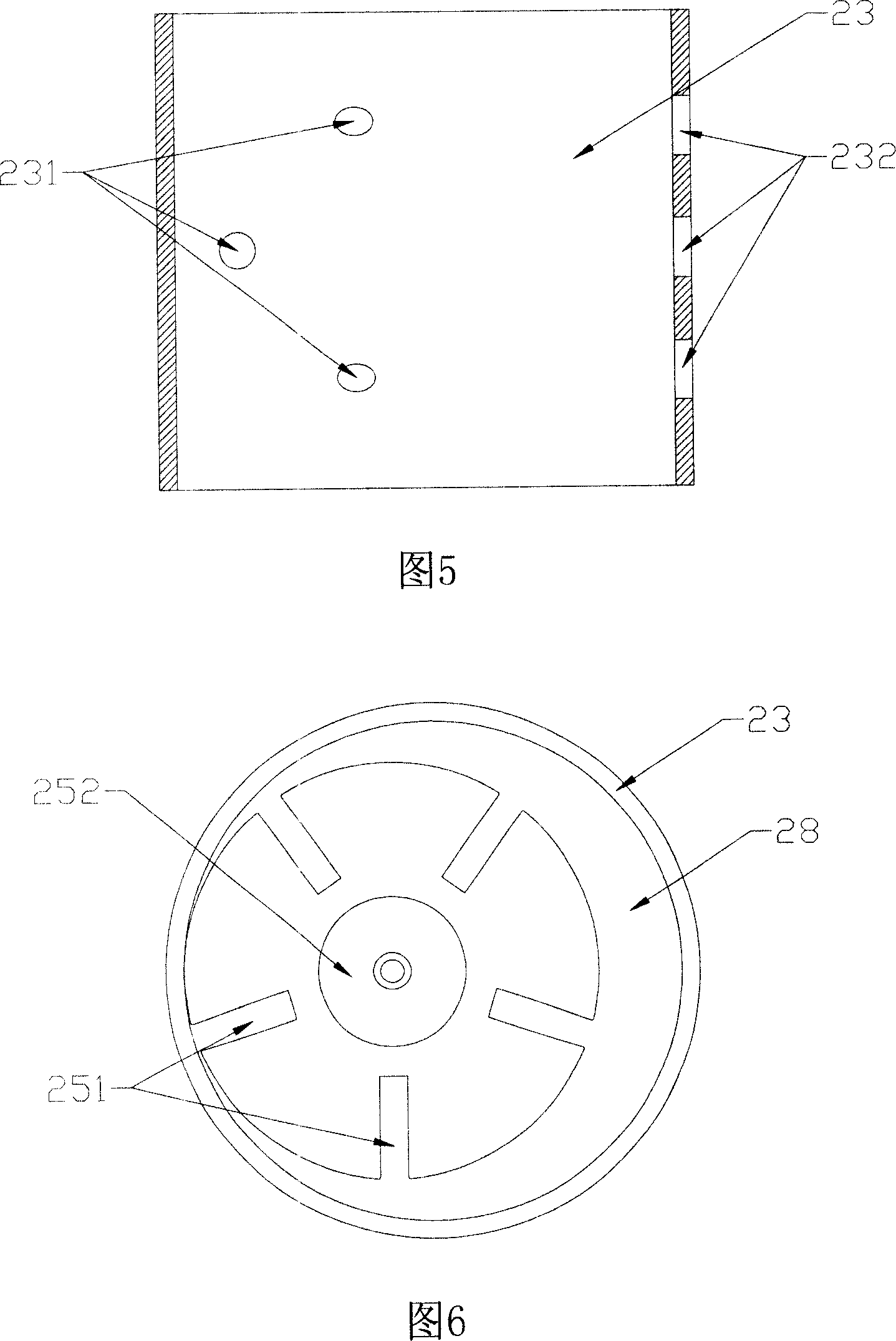
[0022] Described cylinder 23 as shown in Figure 5, outer circumference and inner circumference are concentric, make the wall thickness of whole cylinder wall the same, in order to guarantee enough air gap is left between described cylinder and pneumatic rotor, described cylinder lower seat 22 The inner circumference of the bearing on...


PUM


Abstract

A pneumatic motor is disclosed, the cylinder structure of which is changed to make the bearing at upper seat and the bearing at lower seat eccentric respectively to the internal circumference of the cylinder and make the internal circumference and the external circumference of the cylinder in concentric structure, so that under the precondition of not changing the volume of the cylinder internal chamber, the weight and volume of the whole pneumatic motor are all reduced, its appearance is legerity, for same appearance specification it has higher torque, tools adopting the pneumatic motor will be more agile and convenient.

Description

technical field [0001] The present invention relates to an air motor. Background technique [0002] The vane air motor is a power device widely used in various pneumatic tools and pneumatic machinery. The existing air motor, as shown in Figures 1 and 2, includes a main body 11 and a cylinder lower seat 12 installed in the main body 11, Cylinder 13, blade 14, pneumatic rotor 15 and cylinder upper seat 16, described cylinder lower seat 12 and cylinder upper seat 16 are fixed on the two ends of described cylinder 13, and described pneumatic rotor 15 is placed in it, and on described pneumatic rotor 15 A blade groove 151 for inserting the blade 14 is provided, and two bearings are respectively arranged in the cylinder lower seat 12 and the cylinder upper seat 16, and the inner circumference of the bearing 17 is concentric with the outer circumference of the lower seat 12 or the upper seat 16. , in order to leave an air gap 18 for gas circulation between the pneumatic rotor 15 a...

Claims


Application Information

Patent Timeline
IPC IPC(8): F15B15/08F01C1/344
Inventor 张新和郑雪梅
Owner 郑雪梅
Features
  • Generate Ideas
  • Intellectual Property
  • Life Sciences
  • Materials
  • Tech Scout
  • Unparalleled Data Quality
  • Higher Quality Content
  • 60% Fewer Hallucinations
Learn More