
Large-sized cantilever beams structural load test methods

A load test and cantilever beam technology, which is applied in the testing of machines/structural components, elastic testing, and testing of mechanical components, etc., can solve the problems of increasing testing costs, difficulty in loading large loads, and affecting the smooth progress of testing work, etc. Achieve the effect of shortening the construction period, shortening the test time and improving efficiency

Active Publication Date: 2013-06-26
DALIAN SHIPBUILDING IND
View PDF0 Cites 0 Cited by
  • Summary
  • Abstract
  • Description
  • Claims
  • Application Information

AI Technical Summary

Problems solved by technology

[0003] Aiming at the above problems, the present invention provides a test method for testing the load-bearing capacity of the cantilever beam in a large drilling platform. Going smoothly, the problem of increasing the cost of testing

Method used


Image

  • Large-sized cantilever beams structural load test methods
  • Large-sized cantilever beams structural load test methods

Examples


Embodiment Construction

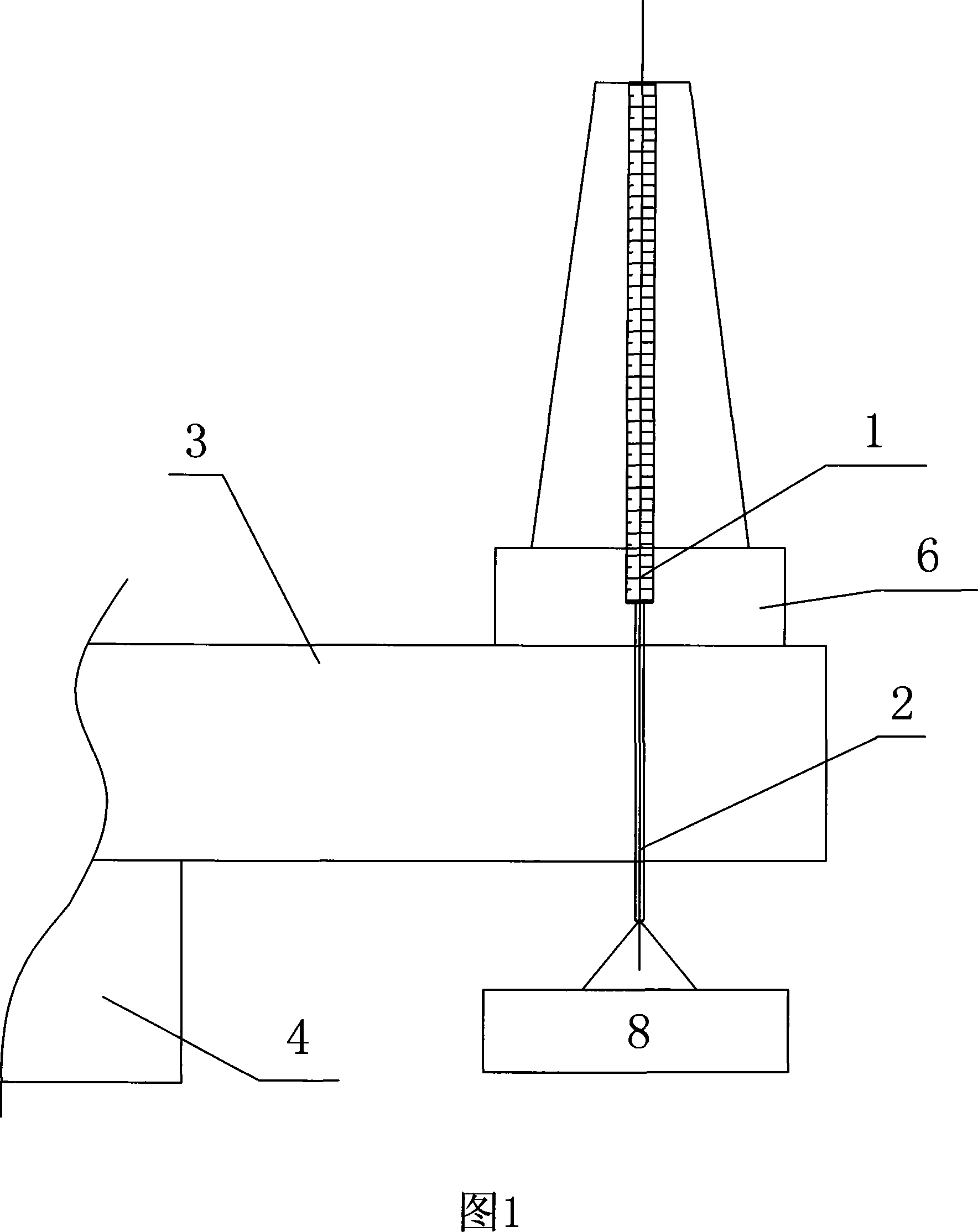
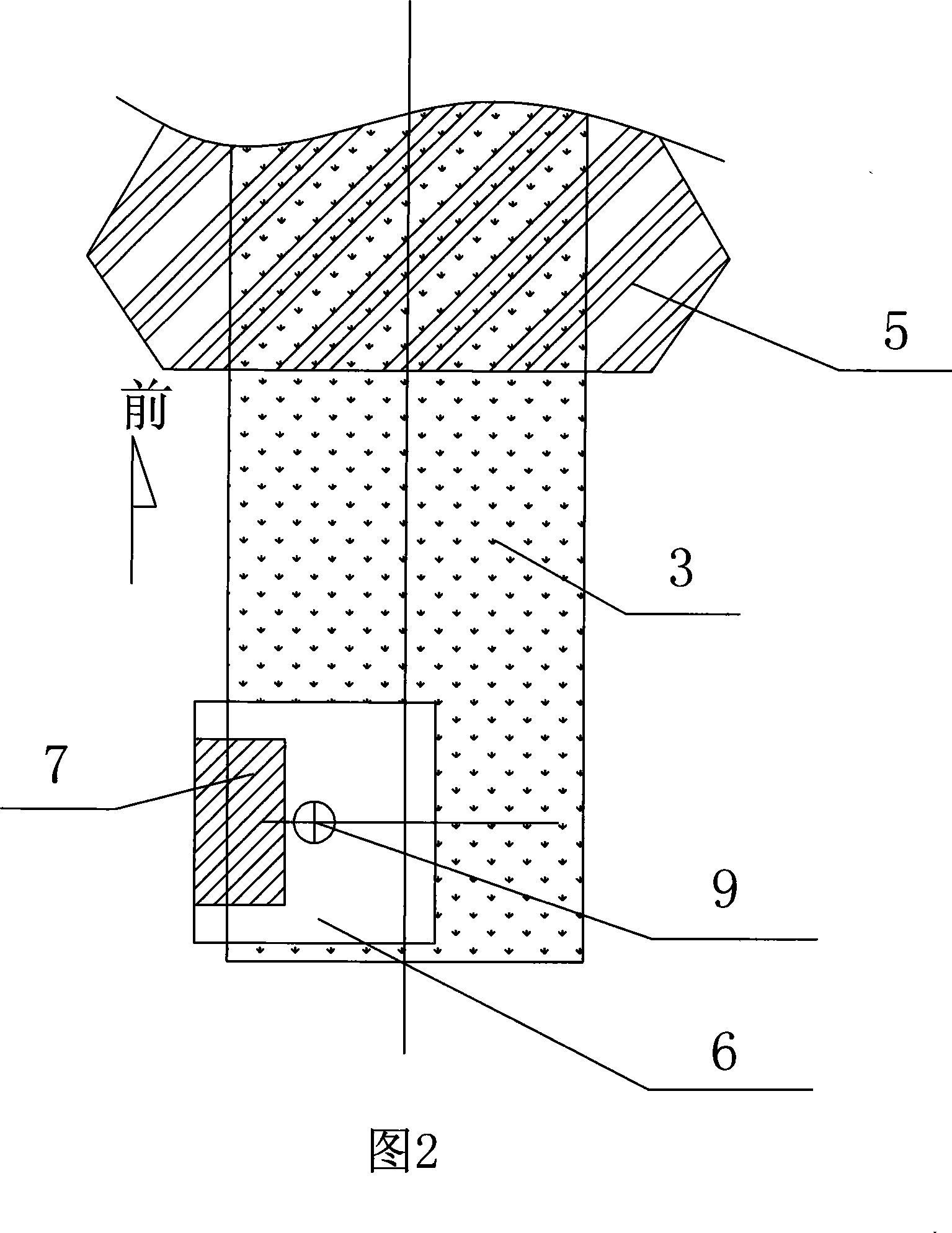
[0013] As shown in Figure 1, the counterweight schematic diagram of the large-scale cantilever beam structure load test method of the present invention, the cantilever beam structure 3 fixed on the main body 4 of the offshore / drilling platform, the drill floor and the drill floor configuration at the front end of the cantilever beam 3 are shown in the figure The top drive 1 (top drive hook), the top drive 1 lifts the load counterweight 8 through the sling 2. Another way of partial loading is shown in FIG. 2 , that is, part of the counterweight is loaded at the stand box 7 (as shown by the shadow). In addition, the counterweight is preferably arranged near the center 9 of the turntable of the drill floor 6 .

[0014] Also shown in Fig. 2 is the platform deck 5, wherein the present invention needs to carry out the counterweight test on the left and right sides of the cantilever beam front end respectively. The so-called starboard and starboard sides, that is, the position of the...


PUM


Abstract

The invention is used for equitably distributing the balance weight of the cantilever in condition of rated maximal load. It comprises: adding a balance weight in the pipe set back at the drill stand; making drill stand at the front of the cantilever located at the quarterpoint side of the cantilever; using the top driver on the drill stand hang up the balance weight.

Description

technical field [0001] The invention relates to a test method for the load strength of a cantilever beam structure, in particular to a method for testing the load-bearing capacity and deflection of the cantilever beam structure during the construction of a drilling platform. Background technique [0002] The large-scale cantilever beam structural load test is mainly aimed at testing the load capacity of large-load cantilever beams in shipbuilding, offshore platforms and construction fields, so as to ensure safe and reliable actual use. In the prior art, the cantilever beam load test is all aimed at the cantilever beam of the small drilling platform, and its load is generally only loaded on the middle part of the cantilever beam. For large drilling platforms, due to the large structure of the cantilever beam, if the above test method is followed, the load at the middle of the cantilever beam is too large, usually reaching 1400 tons or even higher. Therefore, some countries u...

Claims


Application Information

Patent Timeline
Patent Type & Authority Patents(China)
IPC IPC(8): G01M5/00G01M13/00G01M99/00
Inventor 孙洪国高真所孙瑞雪窦钧迟安峰东方伞立忠
Owner DALIAN SHIPBUILDING IND
Learn More