Insertion section for endoscope

A technology for inserting parts and endoscopes, which is applied in material excitation analysis, surgery, fluorescence/phosphorescence, etc., and can solve the problems such as the configuration of the illumination optical system is not specially described, the illumination light is shielded, and it is not considered.

Inactive Publication Date: 2008-03-05
OLYMPUS CORP
View PDF1 Cites 19 Cited by
  • Summary
  • Abstract
  • Description
  • Claims
  • Application Information

AI Technical Summary

Problems solved by technology

[0006] However, in the endoscope described in Japanese Patent Application Laid-Open No. 06-154155, it is not considered that when mucous membranes, blood, dirt, etc. The liquid or gas cleaning performance of the air-supply and water-supply nozzle that cleans the outer surface of each illumination optical system has the problem that sufficient illumination light cannot be irradiated to the inspected part.
Moreover, in the large intestine as a body cavity, for example, there is also a problem that the two illumination optical systems are covered by folds existing in the intestine so that the illumination light to the above-mentioned part to be examined is blocked.
[0010] However, in the endoscope described in Japanese Patent Application Laid-Open No. 06-154155, the arrangement of the illumination optical system for special light observation such as fluorescence observation is not particularly described, and there are problems based on the above-mentioned contents.

Method used


Image

  • Insertion section for endoscope
  • Insertion section for endoscope
  • Insertion section for endoscope

Examples


no. 1 Embodiment approach

[0029] Next, a first embodiment of the present invention will be described with reference to the drawings.

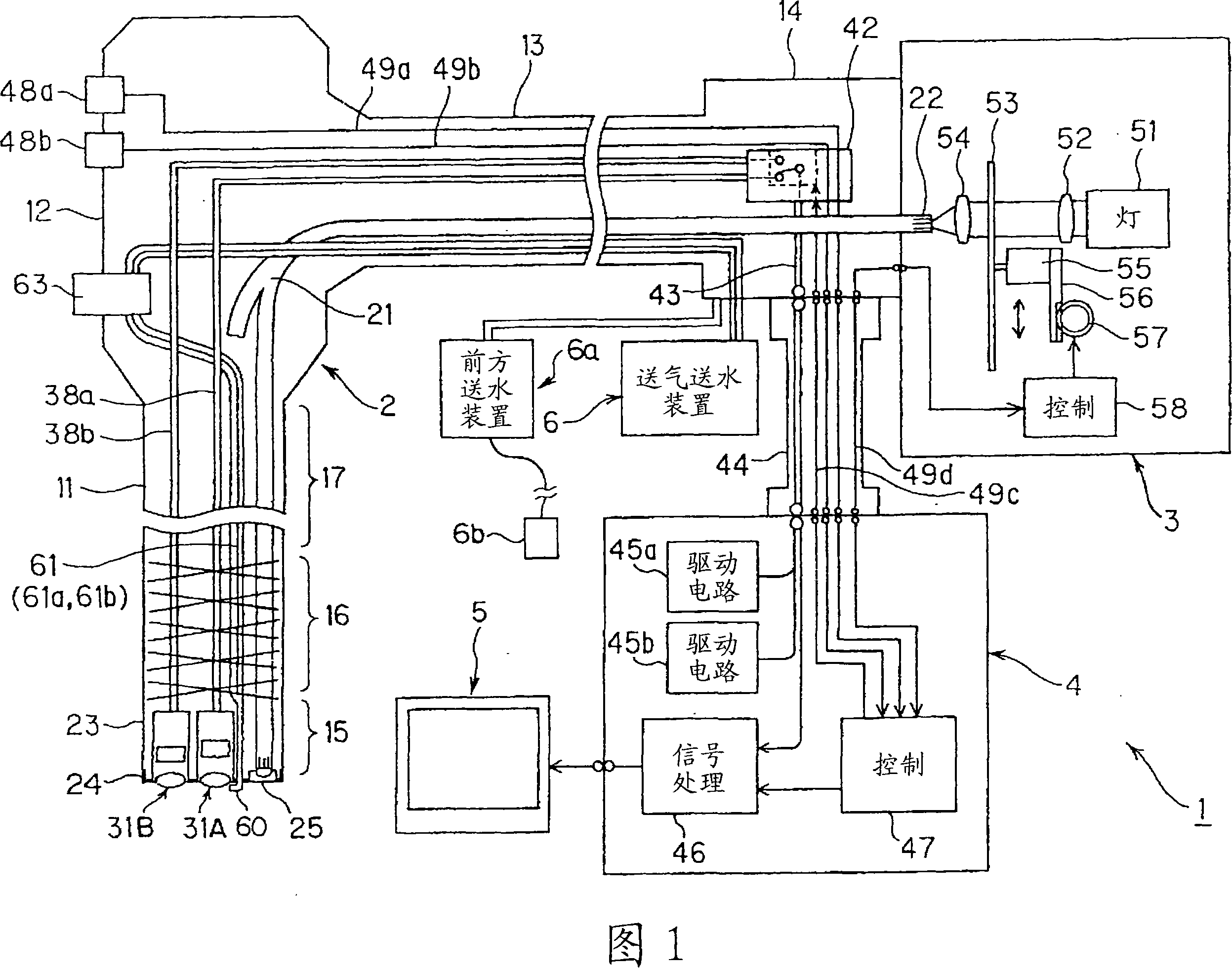
[0030] First, the configuration of an endoscope system according to the present embodiment will be described with reference to FIG. 1 . FIG. 1 is an explanatory diagram schematically showing the configuration of an endoscope system according to a first embodiment of the present invention.

[0031] The endoscope system 1 of this embodiment shown in FIG. 1 has: an endoscope 2 capable of ordinary light observation and fluorescence observation; Processor 4 as a signal processing device for signal processing; Monitor 5 for displaying each endoscopic image for general observation or fluorescence observation by inputting the video signal output from this processor 4; device 6; and a front water delivery device 6a for front water delivery.

[0032] The endoscope 2 has: an elongated endoscope insertion portion (hereinafter simply referred to as an insertion portion) 11 that is...


PUM


Abstract

An insertion section for an endoscope has a distal end; a first imaging means for obtaining a first observation image; a second imaging means provided at the distal end and obtaining a second observation image; a first objective optical system provided at the distal end and collecting imaging light enters into the first imaging means; a second objective optical system provided at the distal end and collecting imaging light enters into the second imaging means; and illumination optical systems arranged at the distal end so as to individually position the first objective optical system and the second objective optical system between the illumination optical systems and applying light to a subject. By this construction, the amount of illumination light necessary for the plurality of imaging means can be distributed to sufficiently exhibit excellent observation performance.

Description

technical field [0001] The present invention relates to an endoscope insertion portion of an endoscope having a plurality of observation optical systems. Background technique [0002] Conventionally, endoscopes have been widely used in the medical field and the like. The endoscope, for example, can observe internal organs and the like in the body cavity by inserting the elongated insertion portion into the body cavity, and can perform various treatments using a treatment instrument inserted into the treatment instrument insertion channel as needed. A curved portion is provided at the distal end of the insertion portion, and the observation direction of the observation window at the distal end portion can be changed by operating the operating portion of the endoscope. [0003] Generally, when the outer surface of the objective optical system of an endoscope is inserted into a body cavity, bodily fluids and the like may adhere to obstruct observation, so air and water nozzles...

Claims


Application Information

Patent Timeline
Patent Type & Authority Applications(China)
IPC IPC(8): A61B1/00G01N21/64
Inventor 大田原崇
Owner OLYMPUS CORP
Why Eureka
Try Eureka